Liquid crystal lens array device, imaging device and imaging method
A liquid crystal lens array and device technology, applied in instruments, nonlinear optics, optics, etc., can solve problems such as affecting the aperture ratio and excessive spacing, and achieve the effects of high aperture ratio, increased duty ratio, and improved imaging quality.
- Summary
- Abstract
- Description
- Claims
- Application Information
AI Technical Summary
Problems solved by technology
Method used
Image
Examples
Embodiment 1
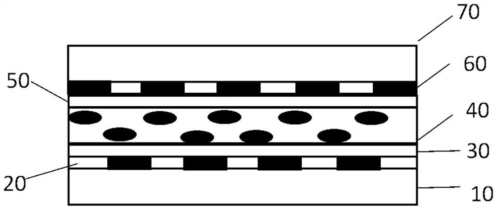
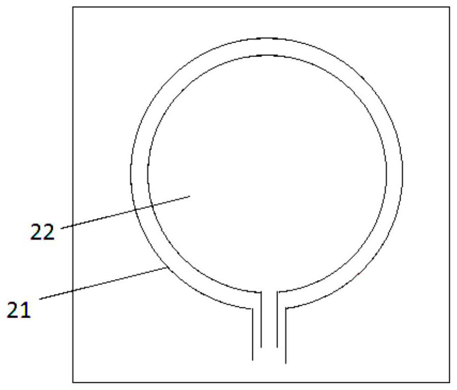
[0035] See figure 1 with figure 2 as well as image 3 , Embodiment 1 of the present invention provides a liquid crystal lens array device, its structure includes: first substrate 10, first array electrode 20, first alignment layer 30, liquid crystal layer 40, second alignment layer 50, second array electrode 60 and the second substrate 70. Wherein the first substrate 10 and the second substrate 70 are preferably glass substrates. Such as figure 2As shown, the first electrode array 20 includes a plurality of first electrode pairs 20 , and the first electrode pairs 20 are ring-shaped and include first electrodes 21 and second electrodes 22 . Likewise, the second electrode array 60 includes a plurality of second electrode pairs 60 , the second electrode pairs 60 are similar in shape to the first electrode pairs, and also have a ring shape, including third electrodes and fourth electrodes. Wherein the projection of the first electrode pair of the first array electrode 20 on...
Embodiment 2
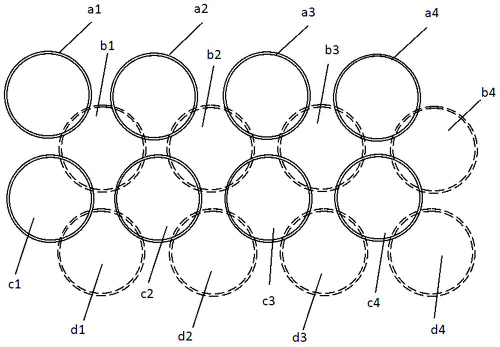
[0039] See Figure 4 with Figure 5 , the liquid crystal lens array device of the second embodiment of the present invention, compared with the liquid crystal lens array device of the first embodiment of the present invention, the main difference is that: two adjacent first electrodes of the first array electrode on the first substrate The pairs are tangent to each other, two adjacent second electrode pairs of the second array electrode on the second substrate are tangent to each other. Such as Figure 4 with Figure 5 , taking the first array electrode as an example, among the ring-shaped first electrode pairs a1, a2, a3 and a4 in the first row, any two adjacent first electrode pairs such as a1 and a2 are tangent to each other, and a1 and C1 among the ring-shaped second electrode pairs c1, c2, c3, and c4 in the adjacent second row is tangent, that is, each ring-shaped first electrode pair is in phase with the adjacent ring-shaped first electrode pair. cut. However, the p...
Embodiment 3
[0045] See Image 6 The main difference between Embodiment 3 of the present invention and Embodiment 1 of the present invention is that in Embodiment 3 of the present invention, a first transparent glass substrate (also called white glass) 80 is added between the first array electrode 20 and the first alignment layer 30, A second transparent glass substrate 90 is added between the second array electrode 60 and the second alignment layer 50 . By arranging the first transparent glass substrate 80 and the second transparent glass substrate 90, when a voltage is applied to the first array electrode and the second array electrode, an inhomogeneous electric field distribution can be better formed, which is conducive to the formation of a gradient index electric field distribution, thereby improving the liquid crystal lens effect. The first transparent glass substrate and the second transparent glass substrate can be ordinary glass. By using the refractive index and insulating prope...
PUM
| Property | Measurement | Unit |
|---|---|---|
| aperture size | aaaaa | aaaaa |
| porosity | aaaaa | aaaaa |
Abstract
Description
Claims
Application Information
 - R&D
- Intellectual Property
- Life Sciences
- Materials
- Tech Scout
- Unparalleled Data Quality
- Higher Quality Content
- 60% Fewer Hallucinations
Browse by: Latest US Patents, China's latest patents, Technical Efficacy Thesaurus, Application Domain, Technology Topic, Popular Technical Reports.
© 2025 PatSnap. All rights reserved.Legal|Privacy policy|Modern Slavery Act Transparency Statement|Sitemap|About US| Contact US: help@patsnap.com


