Medical equipment operation fault monitoring circuit
A technology of operating faults and monitoring circuits, which is applied in the medical field, can solve problems such as medical accidents, reduce treatment efficiency, and medical staff cannot find them in time, so as to avoid medical accidents and facilitate judgment
- Summary
- Abstract
- Description
- Claims
- Application Information
AI Technical Summary
Problems solved by technology
Method used
Image


Examples
Embodiment 1
[0023] A medical equipment operating fault monitoring circuit, such as figure 1As shown, it includes a power supply circuit 1, a first monostable delay circuit 2, a controllable multivibrator circuit 3, a second monostable delay circuit 4, a buzzer circuit 6, a relay circuit 7, a photoelectric Circuit 8, sensor 9 and single-chip microcomputer control circuit 10, the output end of the first monostable delay circuit 2 is connected with the input end of the controllable multivibrator circuit 3, the controllable multivibrator circuit 3 Output end is connected with the input end of relay circuit 7, and the output end of described second monostable delay circuit 4 is connected with the input end of buzzer circuit 6, and described first monostable delay circuit 2 and the second The input end of monostable delay circuit 4 is all connected with the output end of photoelectric circuit 8, and the input end of described photoelectric circuit 8 is connected with the output end of single-ch...
Embodiment 2
[0026] On the basis of Example 1, such as figure 1 As shown, it also includes a two-digit digital tube circuit 5 and a display control circuit 11, the output terminal of the single-chip microcomputer control circuit 10 is connected to the input terminal of the display control circuit 11, and the output terminal of the display control circuit 11 is connected to the two-digit digital The input terminal of the tube circuit 5 is connected, and the power supply circuit 1 supplies power for the two-digit digital tube circuit 5 and the display control circuit 11.
[0027] The sensor 9 can detect the state of the medical equipment, and input the detected data into the single-chip microcomputer control circuit 10, the single-chip microcomputer control circuit 10 inputs the data into the display control circuit 11, and the display control circuit 11 controls the two-digit digital tube circuit 5 to work , the two-digit digital tube circuit 5 displays the parameters of the medical equipme...
Embodiment 3
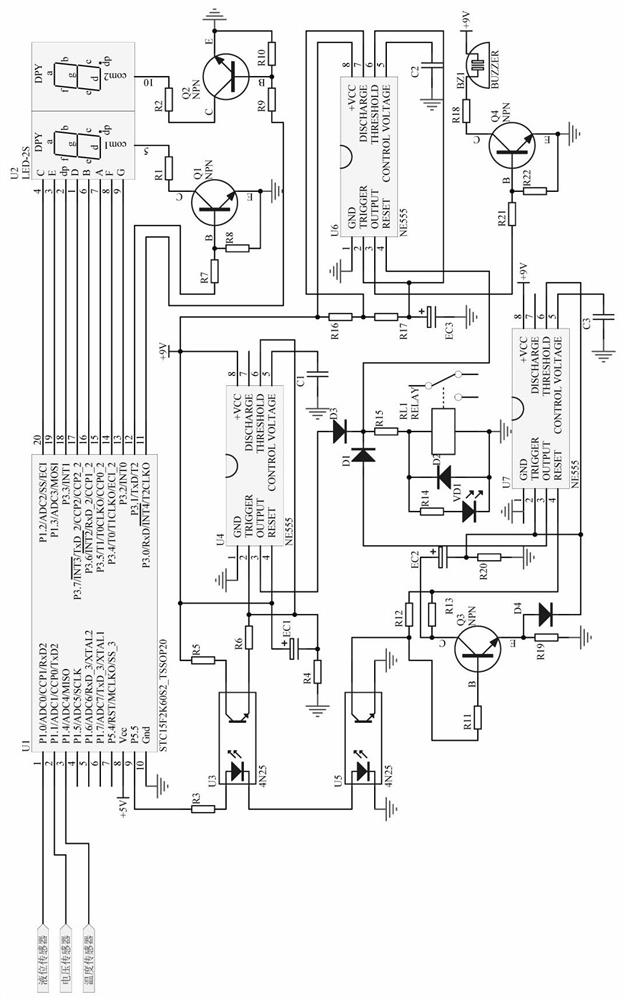
[0029] A medical equipment operating fault monitoring circuit, such as figure 2 As shown, the single-chip control circuit 10 is a single-chip microcomputer STC15F2K60S2_TSSOP20-U1, the 8-pin of the single-chip microcomputer STC15F2K60S2_TSSOP20-U1 is connected to +5V, and the 10-pin of the single-chip microcomputer STC15F2K60S2_TSSOP20-U1 is grounded.
[0030] The photoelectric circuit 8 includes a photocoupler 4N25-U3, a photocoupler 4N25-U5, a resistor R3 and a resistor R5, the anode of the photocoupler 4N25-U3 is connected to one end of the resistor R3, and the other end of the resistor R3 One end is connected to pin 9 of the single-chip microcomputer STC15F2K60S2_TSSOP20-U1, the cathode of the photocoupler 4N25-U3 is connected to the anode of the photocoupler 4N25-U5, the cathode of the photocoupler 4N25-U5 is grounded, and the photocoupler 4N25 - the collector of U5 is grounded, the collector of the photocoupler 4N25-U3 is connected to one end of the resistor R5, and the...
PUM
 Abstract
Description
Claims
Application Information