Processing device and processing technology of heat-insulation cold-proof gloves

A processing device and glove technology, applied to gloves, clothing, protective clothing, etc., can solve the problems of increasing the labor load of the staff, difficulty in adapting to large-scale production, and low efficiency

Pending Publication Date: 2021-09-03
会同县龙凤皮制品有限责任公司
0 Cites 0 Cited by

AI-Extracted Technical Summary

Problems solved by technology

[0004] During the production and processing of gloves, they need to be cleaned and dried. In the prior art, after the gloves are cleaned, the gloves need to be taken out from the clean...

Method used

Concrete, as shown in Figure 2 and Figure 3, the bottom of rotating plate 4 is fixed limit pin 9, and the upper surface wall of processing box 11 has the limit hole 16 that is suitable for limit pin 9, and stirs After the member 27 or the pressing member 24 enters the inside of the processing box 11, the limit pin 9 engages with the limit hole 16 to limit the moving plate 2 and prevent the rotating plate 4 from rotating.
Concrete, as shown in Figure 3, the bottom of water filter plate 20 is equipped with the roller 18 that matches with eccentric wheel 19, and roller 18 has avoided the friction between eccentric wheel 19 and water filter plate 20, in making While the water filter plate 20 vibrates more smoothly, the abrasion between the water filter plate 20 and the eccentric wheel 19 is also reduced, thereby improving the service life of the device.
D. control the rotation of rotating plate 4 by motor one 5, so that pressing member 24 is positioned at the top of processing ca...

Abstract

The invention discloses a processing device for heat-insulation cold-proof gloves. According to the device, under the action of a third motor, a threaded rod and a moving plate, a pressing part and a stirring part can be driven to move in a vertical direction; under the action of a first motor, a rotating plate can rotate, so the pressing part and the stirring part can both enter a treatment box; under the action of a second motor, the stirring part can stir gloves so as to realize cleaning of the gloves; under the action of an electric push rod, a pressing piece can extrude the gloves and discharge water in the gloves outwards; under the action of an air heater, the gloves can be dried; under the action of an eccentric wheel and a spring, a water filtering plate can drive the gloves to vibrate, so a contact area between the gloves and hot air flow is increased, and the drying effect of the gloves are better; and compared with a traditional cleaning and drying mode, the device has the advantages that the gloves do not need to be taken out, an automation degree is higher, efficiency is higher, and the device can adapt to different use environments.

Application Domain

GlovesProtective garment

Technology Topic

Electric machineryAir heater +3

Image

  • Processing device and processing technology of heat-insulation cold-proof gloves
  • Processing device and processing technology of heat-insulation cold-proof gloves
  • Processing device and processing technology of heat-insulation cold-proof gloves

Examples

  • Experimental program(1)

Example Embodiment

[0039] In order to make the objects, technical solutions, and advantages of the present invention more clearly, the technical solutions in the embodiments of the present invention will be described in contemplation in the embodiments of the present invention, and will be described, and the embodiments described in the embodiments of the present invention will be described. It is a part of the embodiments of the present invention, not all of the embodiments. Components of the embodiments of the present invention described and illustrated in the drawings herein can be arranged and designed in various configurations. Thus, the following detailed description of the embodiments of the invention as provided in the drawings are not intended to limit the scope of the invention, but only the selected embodiments of the present invention are shown. Based on the embodiments of the present invention, those of ordinary skill in the art will belong to the scope of the present invention without all other embodiments obtained without creative labor.
[0040] In the description of the invention, it is to be described in the terms "center", "upper", "lower", "left", "right", "vertical", "horizontal", "within", "outside", etc. The orientation or positional relationship indicated is based on the orientation or positional relationship shown in the drawings, is merely intended to describe the present invention and simplified description, rather than indicating or implying that the device or component must have a specific orientation. Construct and operation, so it is not understood to be the limitation of the invention. Moreover, the term "first", "second", "third" is only used to describe purposes, and cannot be understood as an indication or implies relative importance.
[0041] In the description of the invention, it is also needed to be, unless otherwise expressly specified and defined, the term "setting", "mount", "connected", "connection" should be used to understand, for example, can be fixed connection, It is also possible to be detachable, or integrally connected; it can be a mechanical connection, or an electrical connection; it can be directly connected, or the intermediate medium can be interconnected, which may be in the interior of the two elements. For those skilled in the art, the specific meaning of the above terms can be understood in terms of specific cases.
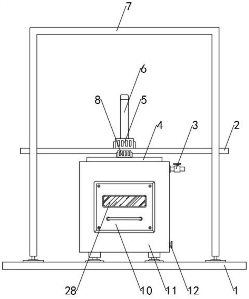
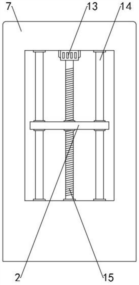
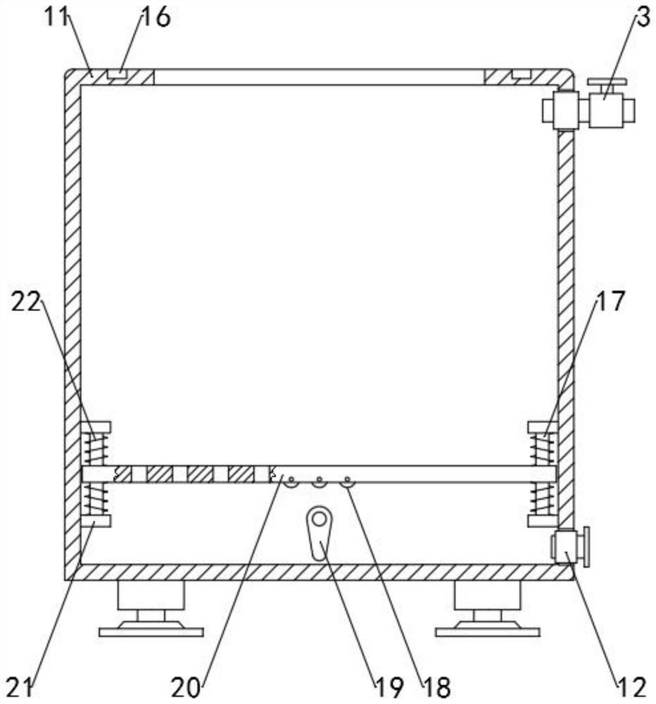
[0042] See Figure 1-5The present invention provides a technical solution: a thermal barrier gloves, cold processing apparatus comprising an open top end 11 and the treatment tank inlet 11 mounted on the treatment tank 3, a drain 12 and the door 10, the door 10 may be added to the internal processing of the glove box 11, and further comprising a base mounted on the base 1, inverted U-shape of the door frame 7, both side walls each having a door frame 7 is provided between the cavity and the two cavities moving plate 2 in the horizontal direction, the movable plate 2 and the snug fit of the cavity, through a threaded rod with a vertical direction of the moving plate 15 and the end of the threaded rod 15 is provided with a threaded rod 15 rotatably drives three motors 13, a threaded rod rotatably connected to the inner wall of the cavity 15 through a bearing, three motor 13 is fixed on the inner wall of the cavity, the output shaft of the motor 13 with three threaded drive rod 15 is connected to a motor 5 is fixed to a motor 5 and the moving plate 2 the output terminal is fixed to the rotating plate 4, a motor 5 is opened, the output shaft of the motor 5 may be driven by a rotary plate 4 rotates with, the rotating plate 4 symmetrically mounted two electric push rod 6 and the motor 8, the motor output of the two 8 equipped with a stirring member 27, to open the two motor 8, the output shaft of the motor 8 may be driven by two stirring member 27 from rotating, the stirring member 27 is rotated to drive the glove, the glove so that cleaning state, electric retractable push rod end 6 of the fixing bracket 26 by there pressing member 24, an electric push rod 6 can be driven by the pressing member 24 of the bracket 26 in the vertical direction, the pressing member 24 for pressing glove, may be discharged outside the water inside the glove, the stent 26 inverted U-shape is provided, on both sides of the push rod 6 is provided with an electric fan heater 23, hot air 23 is mounted on the rotating plate 4, the processing tank 11 is provided with a drainage lumen plate 20 in the horizontal direction and the treatment board 20 through the guide bar 17 in the vertical direction of the two, having a through-hole treatment board 20, between the inner wall to facilitate drainage, drainage plate 20 and two guide rods 17 slip fit, two guide rods 17 and 11 of the process tank connecting block 21 is fixedly connected by a connecting block 21 for the two guide rods 17 are fixed, treatment board 21 and the connecting block 22 by an elastic spring 20 is connected between both ends of spring 22 are respectively connected to drainage plate 20 and the block 21 abutting the bottom plate 20 is provided with a drainage eccentric wheel 19 mounted eccentric drive member 19 is rotated on the treatment tank 11.
[0043] Specifically, such as Figure 4 with Figure 5 , The pressing member comprises a pressing housing 24 by a housing consisting of two fan-shaped 2401, housing 2401 and the pressing bracket 26 is fixedly connected to the pressing interior of the housing 2401 is provided with two fan-shaped form pressure plate 2402 is provided, the pressing plate 2402 and the housing 2401 rotates with the pressing, the pressing plate 2402 is fixed to the rotation drive motor 25 on a solid four pressing housing 2401, four motor housing 25 is fixed to the pressing 2401 on the front wall, the motor 25 is located in the lumen of four bracket 26.
[0044] Specifically, such as figure 1 with figure 2 , The moving plate 2 through the guide bar has a vertical direction 14, a guide bar 14 is fixedly connected to the inner wall of the cavity at both ends of the vertical guide bar 14 and the movable plate 2 a sliding fit, so that the moving plate 2 can be moved in the vertical direction, the effect of the play of the moving plate 2 stopper.
[0045] Specifically, such as image 3 , The bottom drainage plate 20 is mounted with a cam roller 19 adapted 18, the roller 18 to avoid friction between the eccentric 19 and the drainage plate 20, so that the vibration treatment board 20 is more smoothly At the same time, also it reduces wear between drainage plate 20 and the eccentric 19, to improve the life of the device.
[0046] Specifically, such as figure 2 with image 3 , The rotation of the bottom plate 4 is fixed to a finite bit pin 9, the front wall 11 of the treatment tank 9 has a stopper adapted stopper pin hole 16, or the stirring member 27 to the pressing member 24 into the processing tank 11 after the interior of the stopper pin 9 engaged with the stopper holes 16, the limit of the movable plate 2, the rotary plate 4 rotates avoid occurrence.
[0047] Specifically, such as figure 1 , The door 10 is mounted on the observation window 28, an observation window 28 of transparent acrylic material, through the observation window 28 can be easily in the case of processing staff throughout inside of the tank 11.
[0048] Specifically, such as Figure 1 - Figure 5 FIG An insulated gloves, cold processing technology processing apparatus, comprising the steps of:
[0049]. A door 10 is opened, the glove is placed in the processing tank 11, by adding a water inlet pipe 3 into the interior of the processing tank 11 of the cleaning liquid;
[0050] b. Turn the rotating plate 4 by a 5 controls the motor, so that the stirring member 27 at the top of the processing tank 11, 15 rotate by the motor three 13 controls the threaded rod, since the threaded shaft 15 engages with two rotary moving plate, the moving plate 2 can be driven in rotation plate 4 is moved downward, so that the stirring member 27 to enter the interior of the processing tank 11, stirring member 27 is rotated by a motor 8 controls the two, can drive the stirring member 27 from rotating glove, the glove of the cleaning process;
[0051] c. In After completion of washing, by the water inside the treatment tank 11 drains out drain 12, two off the motor 8, the control by the motor three threaded rod 13 is rotated, the moving plate 15 is driven by the rotating plate 4 2 is moved upward, so that the stirring member 27 from coming out of the inside of the processing tank 11;
[0052] d. rotation of the rotary plate 4 by controlling a motor 5, so that the pressing member 24 at the top of the processing tank 11, 15 is rotated by motor 13 controls the three threaded rods, the moving plate 2 driven by the rotating plate 4 is moved downward, so that the pressing 24 to enter the interior of the processing tank 11 by the motor 25 so that the four pressing the pressing plate 2402 and the housing 2401 staggered distribution, increasing the area of ​​contact between the gloves, so that pressing the glove better effect, by an electric push the lever 6 is pushed down the pressing member 24, the pressing member 24 for pressing gloves, achieve initial drainage, drainage initial completion, by an electric push rod 6 to the pressing member 24 is pulled upward;
[0053] e. four by a motor 25 controls the pressing plate 2402 from rotating, so that the pressing pressure plate 2402 retracts into the interior of the housing 2401, in this state, to avoid blocking airflow 2402 thermal pressing plate, so that the hot air acts directly on the surface of the glove, the glove to help the drying process;
[0054] f. Open the hot air through the drive member 23 and the wheel 19 rotates with the eccentric, under the action of spring 22, treatment board 20 to vibrate led gloves, hot air is blown hot air 23 produced gloves glove drying process, compared with the traditional cleaning, drying manner, no need to remove the glove, a higher degree of automation, more efficient and can be adapted to different environments.
[0055] As described above, only the preferred embodiments of the present invention are preferred, but the scope of the invention is not limited thereto, and any techniques, those skilled in the art, according to the present invention, in accordance with the present invention. And its inventive concept is equivalent to alternative or change, which should be covered within the scope of the invention.

PUM

no PUM

Description & Claims & Application Information

We can also present the details of the Description, Claims and Application information to help users get a comprehensive understanding of the technical details of the patent, such as background art, summary of invention, brief description of drawings, description of embodiments, and other original content. On the other hand, users can also determine the specific scope of protection of the technology through the list of claims; as well as understand the changes in the life cycle of the technology with the presentation of the patent timeline. Login to view more.
Why Eureka
Try Eureka