[0027] The present invention is described in further detail now in conjunction with accompanying drawing. These drawings are all simplified schematic diagrams, which only illustrate the basic structure of the present invention in a schematic manner, so they only show the configurations related to the present invention.
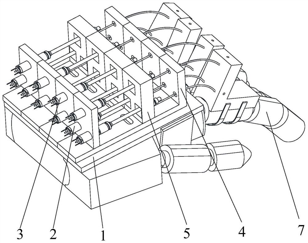
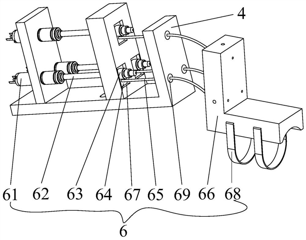
[0028] In the description of the embodiment of the present invention, it needs to be stated that: when the finger rehabilitation robot is worn on the human hand, the direction where the finger points is forward, the direction where the palm is located is the back, the side where the little finger is located is left, and the side where the thumb is located is right , the back side of the palm is the upper side, and the palm side is the lower side, the embodiment of the present invention Figure 1-Figure 7 The hand model 7 is used to replace the patient's hand.
[0029] like Figure 1-Figure 7 The shown specific embodiment of a flexible four-finger rehabilitation robot that can be driven remotely in the present invention includes a dorsal palm fixation assembly 1 worn on the patient's hand, a first finger mechanism 2 and a second finger mechanism 3; the patient The first finger mechanism 2 is worn on the index finger and the little finger, the second finger mechanism 3 is worn on the middle finger and the ring finger; the L-shaped fixing frame 4 is fixed on the back of the palm fixing component 1, and the support frame 5 is fixed on the L-shaped fixing frame 4. A finger mechanism 2 includes a plurality of remote drive devices 6 for driving fingers, and the plurality of remote drive devices 6 of the first finger mechanism 2 are distributed in an isosceles triangle array; the second finger mechanism 3 includes vertically distributed A plurality of distal drive devices 6 in one plane; wherein the dorsal palm fixation assembly 1 includes: the dorsal palm mounting plate 12 fixed below the L-shaped fixing frame 4 and the second straps with both ends fixed on the dorsal palm mounting plate 12 11. The dorsal palm mounting plate 12 is fixed on the back of the palm of the patient through the second strap 11, and the dorsal palm mounting plate 12 is arranged symmetrically on the left and right.
[0030] see figure 2 , Figure 4 and Figure 7 , the remote drive device 6 includes: a drive motor 61 horizontally fixed on the L-shaped fixed frame 4 through a motor support frame, a lead screw 62 coaxially connected with the output shaft of the drive motor 61, a nut sleeved on the lead screw 62 63. The first slider 64 fixedly connected to the nut 63 and the push-pull wire 65 fixedly connected to the first slider 64 at one end; the other end of the push-pull wire 65 passes through the L-shaped bracket 4 and is fixedly connected to the phalanx finger cuff 66, A plurality of slide block guide holes 67 are provided on the support frame 5, and the first slide block 64 slides along the slide block guide holes 67 correspondingly. A plurality of fixing holes 661 are opened on the 66, and the push-pull wire 65 correspondingly extends into the fixing holes 661 and is fixedly connected with the phalanx finger cot 66 through the top wire. The L-shaped fixed frame 4 is provided with a plurality of support holes 41 , and the annular guide block 69 is in interference fit with the support holes 41 . The working principle of the remote driving device 6 is as follows: the driving motor 61 is started, and the leading screw 62 located at the output end of the driving motor 61 is driven to rotate, so that the nut 63 sleeved on the leading screw 62 moves back and forth, so that the first slider 64 moves along the supporting frame. The slider guide hole 67 on the 5 moves back and forth, so that the push-pull wire 65 slides back and forth in the annular guide block 69, thereby controlling the motion of the metacarpophalangeal joints of the fingers. The remote drive devices 6 of the present invention all adopt remote drive, which reduces the weight of the hand wear and is beneficial for patients to carry out rehabilitation training.
[0031] like Figure 1-Figure 2As shown, the first finger mechanism 2 includes three remote drive devices 6 used to drive finger movements, the three remote drive devices 6 are distributed in an isosceles triangle array, and the push-pull wires 65 of the three remote drive devices 6 correspond to Extending into the fixing hole 661 of the phalanx finger cuff 66 , the push-pull wire 65 is fixed by the top wire on the side of the phalanx finger cuff 66 . The action process that the first finger mechanism 2 drives the index finger or little finger to flex or extend: first, according to the length of the patient’s index finger and little finger, adjust the length of the push-pull wire 65 properly and fix it, and then fix the phalange finger cot 66 of the first finger mechanism 2 The first strap 68 is respectively fixed on the patient's index finger and little finger. When the drive motor 61 at the left end of the isosceles triangle base drives the lead screw 62 at the output end of the drive motor 61 to rotate, the lead screw 62 is sleeved on the lead screw 62. The nut 63 of the nut 63 moves, so that the push-pull wire 65 fixed on the nut 63 moves backward, and the drive motor 61 located at the right end of the base of the isosceles triangle drives the lead screw 62 at its output to rotate, so that the lead screw 62 sleeved on the lead screw 62 The nut 63 on the top moves, so that the push-pull wire 65 fixed on the nut 63 moves forward; The movement of the nut 63 on the bar 62 makes the push-pull wire 65 fixed on the nut 63 move forward. The movement of the nut 63 on the lead screw 62 makes the push-pull wire 65 fixed on the nut 63 move backward, and the first finger mechanism 2 can drive the metacarpophalangeal joints of the patient's index finger and little finger to perform adduction/abduction actions. When the drive motor 61 positioned at the vertex of the isosceles triangle drives the lead screw 62 at the output end of the drive motor 61 to rotate, the nut 63 that is sleeved on the lead screw 62 moves, and the push-pull wire 65 fixed on the nut 63 moves to Move forward, make the two driving motors 61 that are positioned at the left and right ends of the base of the isosceles triangle work at the same time, drive the leading screw 62 that is positioned at the output end of the two driving motors 61 to rotate, and make the nuts that are respectively sleeved on the two leading screws 62 63, so that the push-pull wires 65 fixedly connected with the two nuts 63 move backwards, and the first finger mechanism 2 can drive the metacarpophalangeal joints of the patient's index finger and little finger to perform flexion; The driving motor 61 drives the lead screw 62 located at the output end of the drive motor 61 to rotate, so that the nut 63 sleeved on the lead screw 62 moves, and the push-pull wire 65 fixed on the nut 63 moves backward, and at the same time, the The two driving motors 61 at the left and right ends of the bottom of the waist triangle work to drive the leading screw 62 at the output end of the two driving motors 61 to rotate, so that the nuts 63 that are respectively sleeved on the two leading screw 62 move, so that the nuts 63 respectively connected to the two leading screws 62 move. The push-pull wire 65 fixedly connected to the two nuts 63 moves forward, and the first finger mechanism 2 can drive the metacarpophalangeal joints of the patient's index finger and little finger to perform stretching motion. After calculation, the three push-pull wires 65 can move forward/backward in other ways to realize the predetermined trajectory of the metacarpophalangeal joints of the fingers, and the three push-pull wires 65 cooperate with each other to complete the flexion/extension and adduction/abduction of the index finger and little finger .
[0032] like Figure 2-Figure 3 As shown, the second finger mechanism 3 includes two remote drive devices 6 used to drive finger movement, the two remote drive devices 6 are vertically distributed in the same plane, and the push-pull wires 65 of the two remote drive devices 6 Correspondingly extend into the fixing holes 661 of the phalanx finger cuffs 66 , and the push-pull wires 65 are fixed by the top wires on the side of the phalanx finger cuffs 66 . The action process that the second finger mechanism 3 drives the middle finger and ring finger to flex and extend: first, according to the length of the patient's middle finger and ring finger, properly adjust the length of the push-pull wire 65 and fix it, and pass the phalanx finger cot 66 of the second finger mechanism 3 through the second finger mechanism 3. A bandage 68 is respectively fixed on the patient's middle finger and ring finger. When the drive motor 61 of the upper end remote drive device 6 drives the lead screw 62 at the output end of the drive motor 61 to move, the nut 63 sleeved on the lead screw 62 movement, so that the push-pull wire 65 fixedly connected with the nut 63 moves forward, and at the same time, the drive motor 61 of the lower end distal drive device 6 drives the lead screw 62 located at the output end of the drive motor 61 to move, so that it is sleeved on the lead screw The nut 63 on the 62 moves, so that the push-pull wire 65 fixedly connected with the nut 63 moves backward, and the second finger mechanism 3 can drive the metacarpophalangeal joints of the patient's middle finger and ring finger to perform flexion. When the driving motor 61 of the upper remote driving device 6 drives the lead screw 62 at the output end of the drive motor 61 to move, the nut 63 sleeved on the lead screw 62 moves, so that the push-pull wire 65 fixedly connected to the nut 63 Move backwards, and the driving motor 61 of the lower end distal driving device 6 drives the leading screw 62 that is positioned at the output end of the driving motor 61 to move, so that the nut 63 that is sleeved on the leading screw 62 moves, so that it is fixed with the nut 63 The connected push-pull wire 65 moves forward, so that the second finger mechanism 3 can drive the metacarpophalangeal joints of the patient's middle finger and ring finger to stretch. The adduction/abduction process of the middle finger and ring finger adopts the method of follow-up action, which is simple and convenient to control and can play a sufficient rehabilitation effect. The two push-pull wires 65 cooperate with each other to complete the flexion/extension action of the middle finger and ring finger.
[0033] see Image 6 , the push-pull wire 65 extends into the fixing hole 661 of the phalanx finger cuff 66, and is fixed by the top wire located on the side of the phalanx finger cuff 66, and the length of the push-pull wire 65 extending into the fixation hole 661 of the phalanx finger cuff 66 can be adjusted, thereby adjusting the push-pull wire 65 To adapt to the finger lengths of different patients, a rehabilitation robot can realize the training of the patient's left and right hands, saving cost and space.
[0034] The push-pull wire 65 adopts a flexible material with a certain rigidity, which cannot be understood as a limitation of the present invention. The push-pull wire 65 can adopt a nickel-titanium alloy wire or a steel wire rope or a brake wire, which can make wearing more comfortable, avoid causing secondary damage to the patient, and improve security.
[0035] The first slide block 64 and the circular guide block 69 all adopt flexible material, in order to make the first slide block 64 and the circular guide block 69 can slide better, the first slide block 64 and the circular guide block 69 can be Made of elastic plastic or nylon material.
[0036] It should be understood that the specific embodiments described above are only used to explain the present invention, not to limit the present invention. Obvious changes or variations derived from the spirit of the present invention are still within the protection scope of the present invention.