Supercharge Your Innovation With Domain-Expert AI Agents!

Conveying line material box separating device

A separation device and conveying line technology, applied in the field of logistics and warehousing, can solve the problems of increasing operators, easy accumulation, congestion, unfavorable application, etc.

Pending Publication Date: 2021-09-03
QINGDAO KENGIC AUTOMATION EQUIP CO LTD
View PDF7 Cites 0 Cited by
  • Summary
  • Abstract
  • Description
  • Claims
  • Application Information

AI Technical Summary

Problems solved by technology

Due to the fast conveying speed, accumulation and congestion are more likely to occur when a large number of material boxes arrive at this area continuously
If the treatment is not timely, it will further cause the material boxes to squeeze each other and it will be difficult to complete the cleaning in a short time, especially the material boxes at the end are difficult to be taken out
[0004] For the above-mentioned existing common problem of bin accumulation, there is no effective automatic solution at home and abroad. In reality, manual operation is often used for random cleaning
Therefore, it is necessary to increase the number of operators accordingly, which is not conducive to the application of the automatic control technology of the material box conveying line, and at the same time requires additional manual operation space on the basis of difficulty in reducing costs, and the overall efficiency and accuracy of conveying operations are also low

Method used


Image

  • Conveying line material box separating device
  • Conveying line material box separating device
  • Conveying line material box separating device

Examples


Embodiment 1

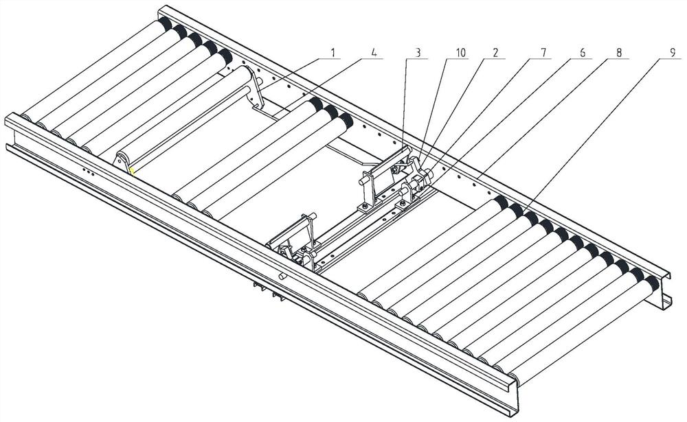
[0031] Example 1, such as Figure 1 to Figure 4 As shown, the material box separation device proposed in this application can be applied to the roller conveyor line 9. The material box separation device includes a roller pressure spring assembly 1 arranged in sequence along the conveying direction and installed on the conveyor line body 8, and a limit stop assembly. 3 and swing assembly 2;

[0032] Wherein, a pull rod 4 is connected between the roller pressing assembly 1 and the swing assembly 2, and a spring 5 is connected between the fuselage 8 and the roller pressing assembly 1;

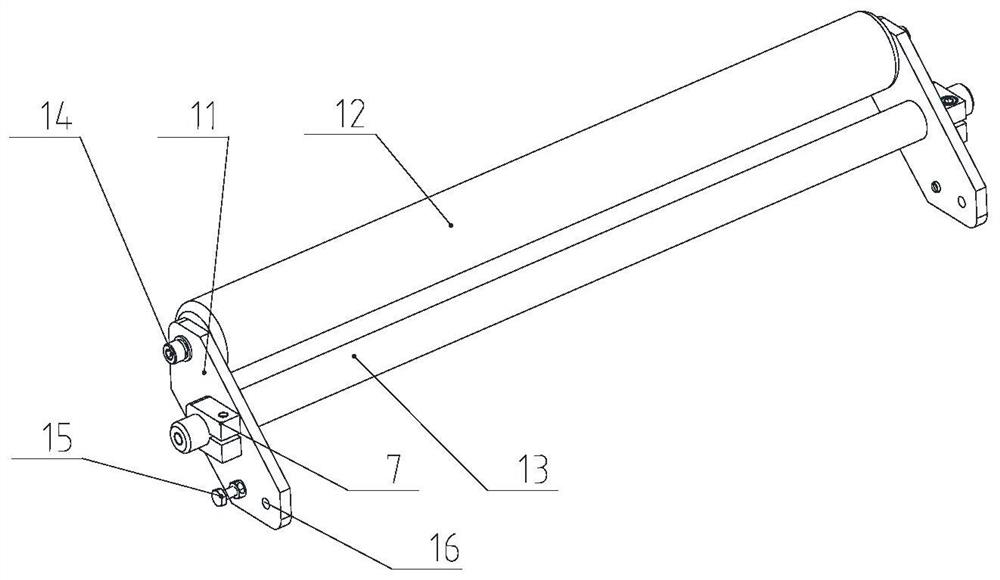
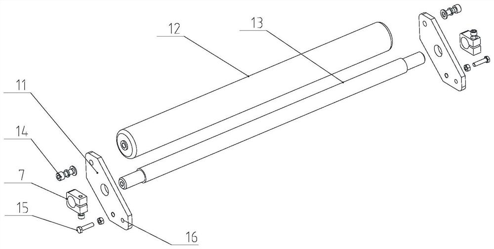
[0033] As shown in FIG. 2 , the roller pressing assembly 1 has a set of roller fixing plates 11, and the two ends of the pressing roller 12 and the roller swing shaft 13 are connected to the roller fixing plates 11 through respectively;

[0034] At the shaft end of the pressing roller 12, it is installed and fixed in the positioning hole of the roller fixing plate 11 through the locking bolt 14; ...


PUM


Abstract

The invention relates to a conveying line material box separating device. A double-rocker linkage separation mechanism is adopted to achieve mutual transmission trigger type automatic separation of material boxes at a front station and a rear station, a control manner that the distance between the rear material box is limited through the front material box is expected to be achieved, and the design purposes of mutual separation of the front material box and the rear material box and ordered conveying are achieved. A separating device comprises a roller pressing and bouncing assembly, a limiting and stopping assembly and a swinging assembly which are sequentially arranged in the conveying direction, a pull rod is connected between the roller pressing and bouncing assembly and the swinging assembly, and a spring is connected to the roller pressing and bouncing assembly in the direction opposite to the pull rod; the roller pressing and bouncing assembly and the swinging assembly swing and rotate in the axial directions of the roller pressing and bouncing assembly and the swinging assembly correspondingly, and the roller pressing and bouncing assembly, the pull rod and the swinging assembly are sequentially connected to form a double-rocker linkage mechanism; and in the process of swinging in the direction opposite to the conveying direction, the swinging assembly forms reverse resistance to the limiting and stopping assembly, and the limiting and stopping assembly stops the material boxes from passing through.

Description

technical field [0001] The invention relates to an automatic separation device applied to a box-type conveying line, which belongs to the field of logistics storage. Background technique [0002] With the rapid improvement of the automation level of e-commerce and manufacturing, the application scale of various box-type conveyor lines is increasing, and the requirements for automatic control of sorting and entering warehouse operation loops are also increasing. [0003] Under the existing equipment layout conditions, there is usually an inclined unpowered conveying section (such as a roller conveying line) at the front and rear ends of the bin conveying line as a delivery or packaging operation area. Due to the fast conveying speed, accumulation and congestion are more likely to occur when a large number of material boxes arrive at this area continuously. If it is not handled in time, it will further cause the material boxes to squeeze each other and be difficult to complet...

Claims


Application Information

Patent Timeline
Patent Type & Authority Applications(China)
IPC IPC(8): B07B13/00B07B13/16B07B13/18
CPCB07B13/00B07B13/16B07B13/18
Inventor 刘真国于付龙李帅邱吉知田伟
Owner QINGDAO KENGIC AUTOMATION EQUIP CO LTD
Features
  • R&D
  • Intellectual Property
  • Life Sciences
  • Materials
  • Tech Scout
  • Unparalleled Data Quality
  • Higher Quality Content
  • 60% Fewer Hallucinations
Learn More