Combined positioning and clamping device

A positioning clamping and combined technology, which is applied in positioning device, clamping, supporting, etc., can solve the problem of single function of the elbow clamp, and achieve the effect of multiple functions, simple and reliable driving mechanism, and simple and reliable structure

Pending Publication Date: 2021-09-03
CHANGZHOU INST OF TECH
View PDF0 Cites 4 Cited by
  • Summary
  • Abstract
  • Description
  • Claims
  • Application Information

AI Technical Summary

Problems solved by technology

[0003] In order to solve the single-function problem of the toggle clamp existing in the prior art, the present invention provides a combined positioning and clamping device

Method used


Image

  • Combined positioning and clamping device
  • Combined positioning and clamping device
  • Combined positioning and clamping device

Examples


Embodiment 1

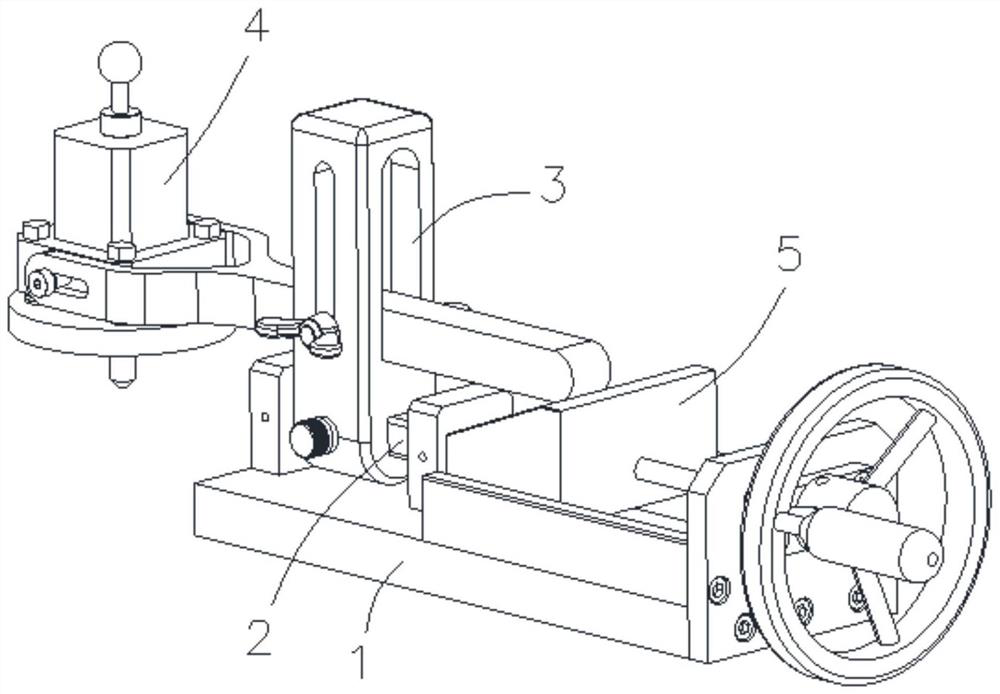
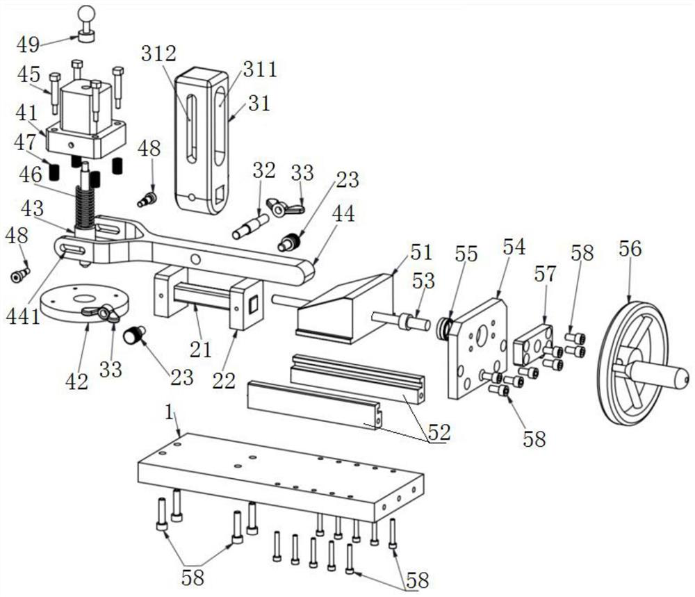
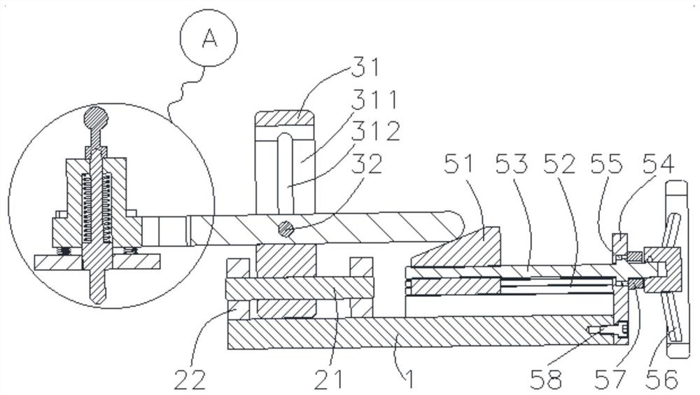
[0026] like Figures 1 to 4 As shown, a combined positioning and clamping device includes a base plate 1, a length adjustment mechanism 2, a height adjustment mechanism 3, a positioning and pressing mechanism 4 and a driving mechanism 5; the positioning and pressing mechanism 4 includes a positioning seat 41, a pressing mechanism Block 42, positioning rod 43 and rocker arm 44, the positioning seat 41 is slidably provided with a guide post 45, one end of the guide post 45 extends a limiting flange 451, and the other end of the guide post 45 is connected to the pressing block 42 is fixedly connected, the positioning rod 43 slides through the positioning seat 41 and the pressing block 42 in turn, the sliding direction of the positioning rod 43 and the guide post 45 are consistent, and a second An elastic member 46, the elastic force direction of the first elastic member 46 is toward the sliding direction of the positioning rod 43, and the positioning end of the positioning rod 43...


PUM


Abstract

The invention particularly relates to a combined positioning and clamping device. The combined positioning and clamping device comprises a bottom plate, a length adjusting mechanism, a height adjusting mechanism, a positioning and pressing mechanism and a driving mechanism. The positioning and pressing mechanism comprises a positioning seat, a pressing block, a positioning rod and a rocker arm. A guide column is slidably arranged on the positioning seat. One end of the guide column extends to form a limiting flange, and the other end of the guide column is fixedly connected with the pressing block. The positioning rod sequentially and slidably penetrates through the positioning seat and the pressing block. The sliding direction of the positioning rod is consistent with that of the guide column. A first elastic piece is arranged between the positioning seat and the positioning rod and faces the sliding direction of the positioning rod. The positioning end, close to the pressing block, of the positioning rod is matched with a positioning hole of a workpiece in shape. One end of the rocker arm is fixedly connected with the positioning seat. The bottom plate, the length adjusting mechanism, the height adjusting mechanism and the rocker arm are sequentially arranged. The length adjusting mechanism is used for adjusting the front-back position of the height adjusting mechanism. The height adjusting mechanism is used for adjusting the height position of the rocker arm. The middle of the rocker arm is connected with the height adjusting mechanism in a rotating mode. The driving mechanism is used for driving the rocker arm to swing up and down.

Description

technical field [0001] The invention belongs to the technical field of clamps, and in particular relates to a combined positioning and clamping device. Background technique [0002] The elbow clamp usually plays the role of clamping parts in the production line or machine tool processing, and is a clamping device that allows the clamped parts to be subjected to construction or inspection. Toggle clamp, also known as toggle clamp, usually uses a connecting rod structure. Manual operation is used to move the control rod, and the working arm is driven to move by the connecting rod structure, so that the indenter on the working arm compresses the parts. However, in actual working conditions, the part not only needs to be clamped, but also needs to be positioned. At present, the existing elbow clamp only has the function of tightening, but not the function of positioning, the structure is complex, the function is single, and the scope of application is small. SUMMARY OF THE IN...

Claims


Application Information

Patent Timeline
Patent Type & Authority Applications(China)
IPC IPC(8): B23Q3/06
CPCB23Q3/06
Inventor 盛冬平戴翔何亚峰门艳忠吴小锋尹飞鸿
Owner CHANGZHOU INST OF TECH
Why Eureka
Try Eureka