A high-strength connection structure and segmented wind turbine blades
A technology for connecting structures and wind power blades, which is applied in the direction of connecting components, wind power generation, and wind power engines consistent with the wind direction. Internal water leakage, the effect of ensuring connection strength and airtightness
- Summary
- Abstract
- Description
- Claims
- Application Information
AI Technical Summary
Problems solved by technology
Method used
Image
Examples
Embodiment 1
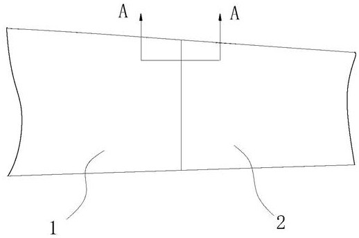
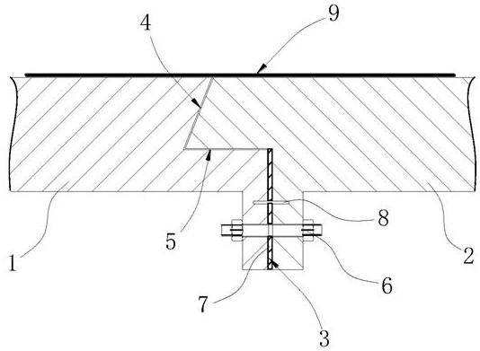
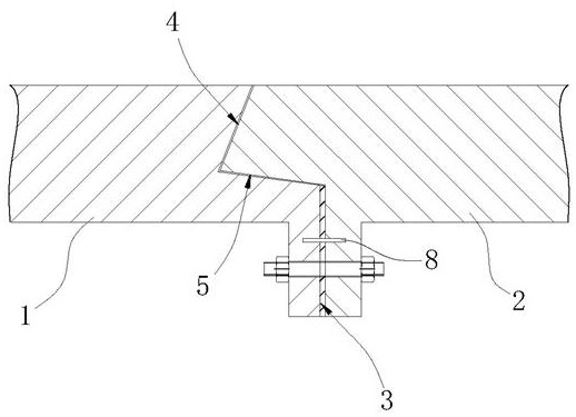
[0049] like Figures 1 to 3 Shown: a high-strength connection structure, including:
[0050] The first segment 1 and the second segment 2 arranged along the length direction of the wind power blade, the first segment 1 and the second segment 2 include:
[0051] A first mating surface 3 extending toward the inside of the wind power blade, the first mating surface 3 being perpendicular to the length direction of the wind power blade;
[0052] A second mating surface 4 that is misaligned with the first mating surface 3, and the second mating surface 4 is misaligned in a direction close to the first segment 1 with respect to the first mating surface 3;
[0053] A connection surface 5, the connection surface 5 connects the first mating surface 3 and the second mating surface 4;
[0054] Connecting bolts 6, the connecting bolts 6 are located in the wind power blades, and pass through the two first mating surfaces 3 to fix the first segment 1 and the second segment 2, and the conne...
Embodiment 2
[0069] like Figures 4 to 7 Shown: The difference from Embodiment 1 is that the second mating surface 4 of the second segment 2 is provided with a bump 21, and the second mating surface 4 of the first segment 1 is correspondingly provided with a groove, and the bump 21 and the concave The slots cooperate with each other to limit the flanging of the second segment 2 to the outside of the wind turbine blade.
[0070] In this embodiment, the anti-flange structure is a protrusion 21 and a groove that cooperate with each other. By setting the protrusion 21 on the second segment 2, the first segment 1 is correspondingly provided with a groove. In the first segment 1 When docking with the second segment 2, the protrusion 21 is inserted into the groove, so that the groove limits the degree of freedom of the protrusion 21, restricts its flipping and movement perpendicular to the length direction of the wind turbine blade, thereby restricting the second segment Segment 2 is flanged tow...
Embodiment 3
[0073] like Figures 8 to 9 Shown: The difference from Example 1 is that the second segment 2 is provided with a pre-embedded screw sleeve 31 on the connecting surface 5, the embedded screw sleeve 31 is located at one end close to the second mating surface 4, and the embedded screw sleeve 31 is vertical In the length direction of the wind turbine blade, the first segment 1 is provided with a corresponding through hole on the connecting surface 5, and a locking bolt 32 is arranged in the through hole, and the locking bolt 32 cooperates with the embedded screw sleeve 31 to restrict the second segment 2. Flanging to the outside of the wind turbine blade.
[0074] In this embodiment, the anti-flange structure is a pre-embedded screw sleeve 31 and a locking bolt 32 that cooperate with each other. By setting the embedded screw sleeve 31 on the connecting surface 5 of the second segment 2, the first segment 1 The connecting surface 5 of the connecting surface 5 is provided with a co...
PUM
 Abstract
Description
Claims
Application Information
 - R&D
- Intellectual Property
- Life Sciences
- Materials
- Tech Scout
- Unparalleled Data Quality
- Higher Quality Content
- 60% Fewer Hallucinations
Browse by: Latest US Patents, China's latest patents, Technical Efficacy Thesaurus, Application Domain, Technology Topic, Popular Technical Reports.
© 2025 PatSnap. All rights reserved.Legal|Privacy policy|Modern Slavery Act Transparency Statement|Sitemap|About US| Contact US: help@patsnap.com


