
Pipe joint deflection and jacking force transmission state monitoring system and method

A condition monitoring system and a technology for pipe joints, which are used in pipeline systems, pipeline laying and maintenance, pipes/pipe joints/pipe fittings, etc. Poor flexibility and other problems, to achieve the effect of convenient pipeline installation and layout, convenient and accurate fast troubleshooting, and improved positioning accuracy

Active Publication Date: 2021-09-03
湖北地建集团神龙市政建设工程有限公司
View PDF7 Cites 0 Cited by
  • Summary
  • Abstract
  • Description
  • Claims
  • Application Information

AI Technical Summary

Problems solved by technology

[0005] Aiming at the deficiencies of the prior art, the present invention provides a pipe joint deflection and jacking force transmission status monitoring system and method, which solves the problem that the existing pipe joint installation monitoring system has low positioning accuracy, and the existing troubleshooting system has relatively poor functions. Single, and the flexibility to deal with different construction conditions on the construction site is poor. It is impossible to design a complete set of pipe joint detection, positioning and troubleshooting systems to enable the entire monitoring system to perform accurate and flexible monitoring. It is impossible to achieve both convenience and accuracy. The purpose of quickly troubleshooting the abnormal pipe joints cannot be realized in a short time to find the abnormal pipe joints for adjustment and processing, which increases the workload of construction personnel and reduces the construction efficiency.

Method used


Image

  • Pipe joint deflection and jacking force transmission state monitoring system and method
  • Pipe joint deflection and jacking force transmission state monitoring system and method
  • Pipe joint deflection and jacking force transmission state monitoring system and method

Examples


Embodiment Construction

[0027] The following will clearly and completely describe the technical solutions in the embodiments of the present invention with reference to the accompanying drawings in the embodiments of the present invention. Obviously, the described embodiments are only some, not all, embodiments of the present invention. Based on the embodiments of the present invention, all other embodiments obtained by persons of ordinary skill in the art without making creative efforts belong to the protection scope of the present invention.

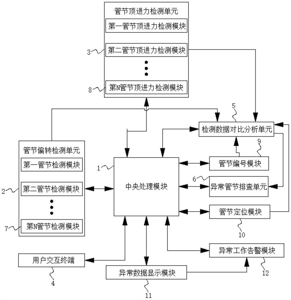
[0028] see Figure 1-3 , the embodiment of the present invention provides a technical solution: a pipe joint deflection and jacking force transmission state monitoring system, including a central processing module 1, a pipe joint deflection detection unit 2, a pipe joint jacking force detection unit 3 and a user interaction terminal 4. Central processing module 1 realizes two-way electrical connection with pipe joint deflection detection unit 2, pipe joint jac...


PUM


Abstract

The invention discloses a pipe joint deflection and jacking force transmission state monitoring system and method. The system comprises a central processing module, a pipe joint deflection detection unit, a pipe joint jacking force detection unit, and a user interaction terminal. The central processing module is bidirectionally and electrically connected with the pipe joint deflection detection unit, the pipe joint jacking force detection unit and the user interaction terminal. The invention relates to the technical field of construction pipeline monitoring. According to the pipe joint deflection and jacking force transmission state monitoring system and method, the whole monitoring system can carry out accurate and flexible monitoring by designing a whole pipe joint detection, positioning and troubleshooting system, the purpose of conveniently and accurately carrying out rapid troubleshooting on abnormal pipe joints is well achieved, the abnormal pipe joints can be found in a short time to be adjusted, the positioning accuracy of the pipe joint installation monitoring system is greatly improved, the workload of constructors is relieved, and the construction efficiency is improved.

Description

technical field [0001] The invention relates to the technical field of construction pipeline monitoring, in particular to a monitoring system and method for pipe joint deflection and jacking force transmission status. Background technique [0002] Building construction refers to the production activities in the implementation stage of engineering construction. It is the construction process of various buildings. It can also be said to be the process of turning various lines on the design drawings into real objects at designated locations. It includes basic engineering construction, main structure construction, roofing engineering construction, and decoration engineering construction. The project management is the sum of a series of work such as the planned collection, processing, storage, transmission, and application of various professional information with the construction project information as the management object. In the construction project information management, the...

Claims


Application Information

Patent Timeline
IPC IPC(8): F16L1/032F16L1/06F17D5/00G08B21/18
CPCF16L1/032F16L1/06F17D5/00G08B21/187
Inventor 段文贵李水明晏剑波郭旭张昌福余磊
Owner 湖北地建集团神龙市政建设工程有限公司
Learn More