
Array substrate and display panel

A technology of array substrate and column direction, which is applied in the direction of instruments, nonlinear optics, optics, etc., to increase the error tolerance rate of the screen, prevent screen dead pixels, and improve production efficiency

Pending Publication Date: 2021-09-03
HKC CORP LTD
View PDF7 Cites 1 Cited by
  • Summary
  • Abstract
  • Description
  • Claims
  • Application Information

AI Technical Summary

Problems solved by technology

[0004] The purpose of this application is to provide an array substrate and a display panel, which solves the problem that the existing thin film transistor needs to be repaired before the pixel structure can work normally.

Method used


Image

  • Array substrate and display panel
  • Array substrate and display panel
  • Array substrate and display panel

Examples


Embodiment approach

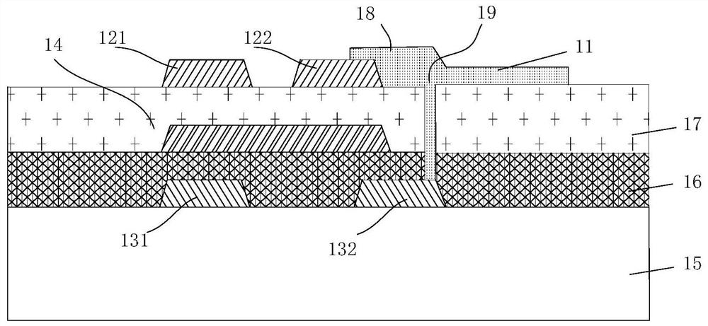
[0050] Of course, the first thin film transistor 12 and the second thin film transistor 13 may not be stacked, but formed on the same layer. For example, the first thin film transistor 12 and the second thin film transistor 13 are arranged on the same layer. A feasible implementation mode, but not limited to this implementation mode, as long as it is applicable:

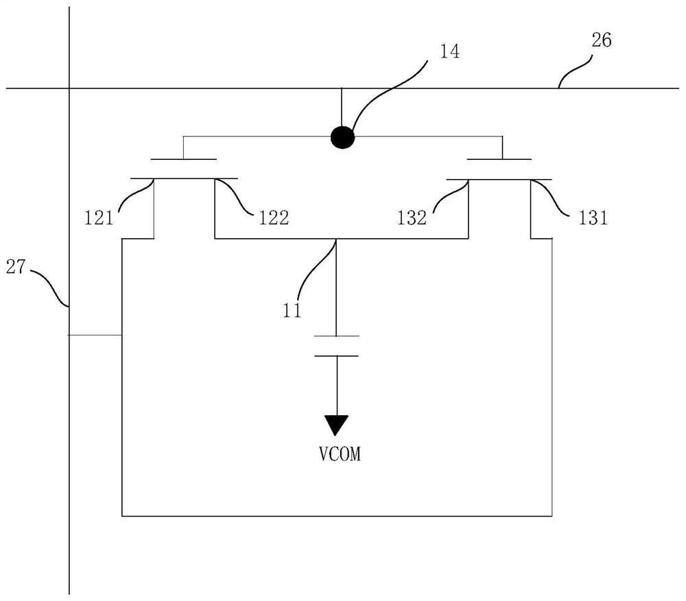
[0051] Figure 4 is a schematic circuit diagram of the pixel structure of the third embodiment of the present application, Figure 5 is a cross-sectional view of the pixel structure of the third embodiment of the present application, combined with Figure 4 and Figure 5 It can be seen that the pixel structure 10 is formed on the array substrate 110, the scan line 26 is also arranged on the array substrate 110, the first gate 123 of the first thin film transistor 12 and the second gate 133 of the second thin film transistor 13 are independent of each other. and are connected to the same scanning line 26 respective...


PUM


Abstract

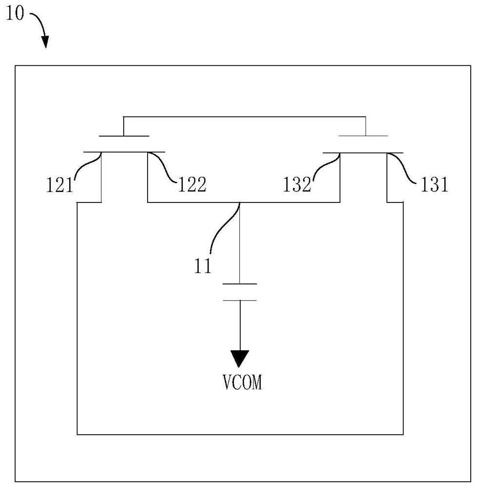
The invention discloses an array substrate and a display panel. The array substrate comprises a substrate, a scanning line, a data line and a pixel structure. The pixel structure comprises a pixel electrode, a first thin film transistor and a second thin film transistor, wherein the first thin film transistor comprises a first source electrode, a first drain electrode and a first grid electrode; the second thin film transistor comprises a second source electrode, a second drain electrode and a second grid electrode; the first drain electrode and the second drain electrode are connected to the pixel electrode, the first source electrode and the second source electrode are connected with each other, and the first grid electrode and the second grid electrode are connected with each other. The two thin film transistors are arranged on one pixel structure, the two thin film transistors act at the same time to control the pixel electrode to be charged, when one thin film transistor is damaged and cannot work normally, the other thin film transistor can work normally to achieve normal data display without being repaired, and the array substrate has the advantages of preventing dead pixels of a screen, and increasing the error-tolerant rate of the screen.

Description

technical field [0001] The present application relates to the field of display technology, and in particular to an array substrate and a display panel. Background technique [0002] Thin Film Transistor Liquid Crystal Display (TFT-LCD) is mainly formed by aligning the array substrate and the color filter substrate and pouring liquid crystal into them. The array substrate is provided with a thin film transistor (Thin Film Transistor, TFT ), the color filter is set on the color filter substrate, and the signal and voltage loaded on each pixel are controlled by the TFT to control the rotation direction of the liquid crystal molecules, so as to control whether the polarized light of each pixel is emitted or not to achieve the display purpose . [0003] In the process of manufacturing array substrates, due to the limitation of process conditions, various defects often occur, such as TFT damage and cannot work normally, and TFT will also be damaged during use. In order to improve...

Claims


Application Information

Patent Timeline
Patent Type & Authority Applications(China)
IPC IPC(8): G02F1/1362G02F1/1368
CPCG02F1/13624G02F1/1368
Inventor 秦福宏康报虹
Owner HKC CORP LTD
Learn More