Foil coil winding method and device for three-dimensional wound core transformer

A technology of three-dimensional wound iron core and winding method, which is applied in the direction of inductance/transformer/magnet manufacturing, coil manufacturing, electrical components, etc., and can solve problems that affect the heat dissipation performance and short-circuit resistance of transformers, high investment in tooling equipment, and reduce production efficiency. , to achieve the effect of improving feeding stability and winding efficiency, improving winding efficiency, and improving automation

Active Publication Date: 2021-09-03
HAIHONG ELECTRIC CO LTD +1
View PDF6 Cites 2 Cited by
  • Summary
  • Abstract
  • Description
  • Claims
  • Application Information

AI Technical Summary

Problems solved by technology

This winding method has problems such as high investment in tooling equipment, long production cycle, reduced production efficiency, and many production processes. Moreover, this winding method will cause an air gap between the foil winding and the iron core, which affects the heat dissipation of the transformer. performance and short-circuit resistance

Method used


Image

  • Foil coil winding method and device for three-dimensional wound core transformer
  • Foil coil winding method and device for three-dimensional wound core transformer
  • Foil coil winding method and device for three-dimensional wound core transformer

Examples


Embodiment Construction

[0026] Embodiments of the present invention are described in detail below, and examples of the embodiments are shown in the drawings, wherein the same or similar reference numerals denote the same or similar elements or elements having the same or similar functions throughout. The embodiments described below by referring to the figures are exemplary only for explaining the present invention and should not be construed as limiting the present invention.

[0027] In the description of the present invention, it should be understood that the orientation descriptions, such as up, down, front, back, left, right, etc. indicated orientations or positional relationships are the orientations or positional relationships shown in the accompanying drawings, for the purpose of It is convenient to describe the present invention and simplify the description, but does not indicate or imply that the device or element referred to must have a specific orientation, be constructed and operate in a s...


PUM


Abstract

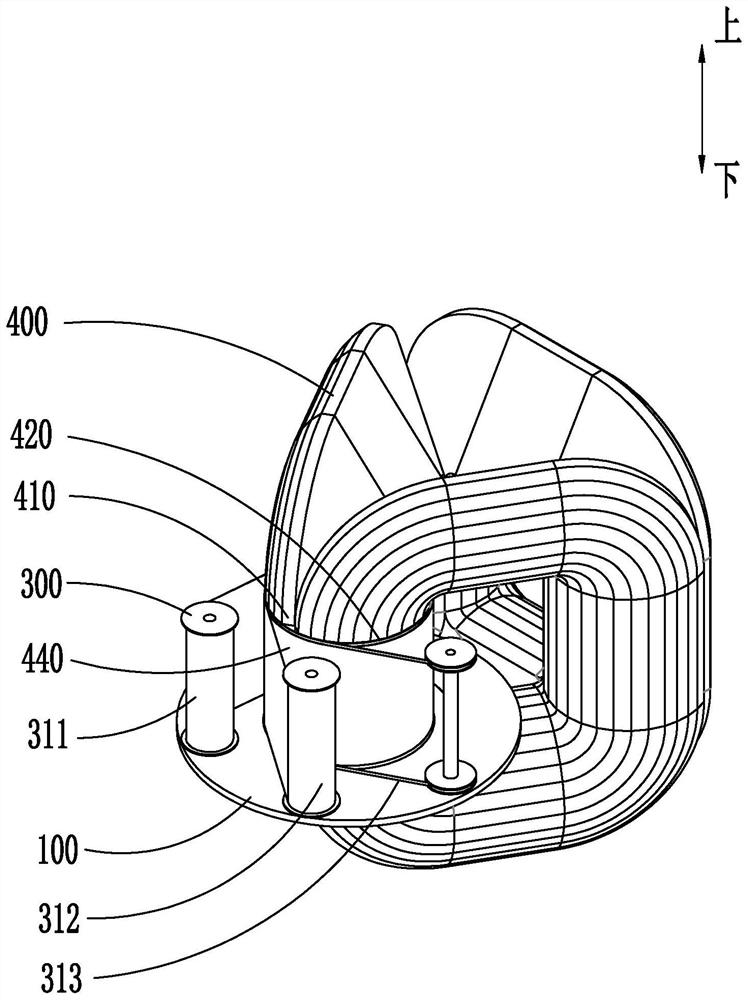
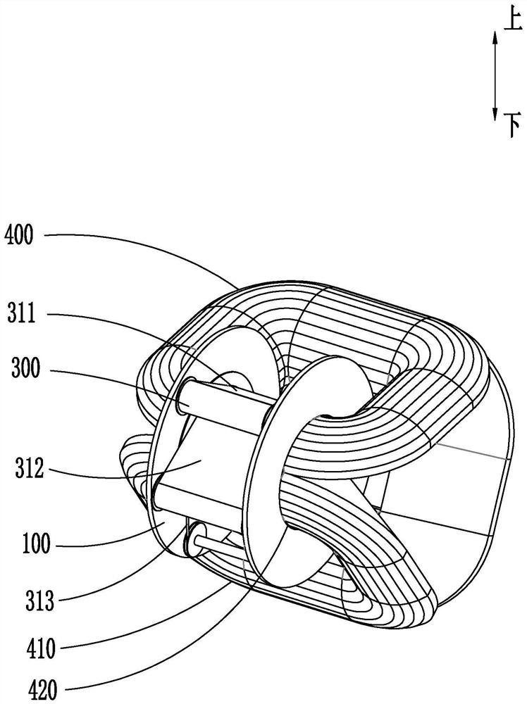
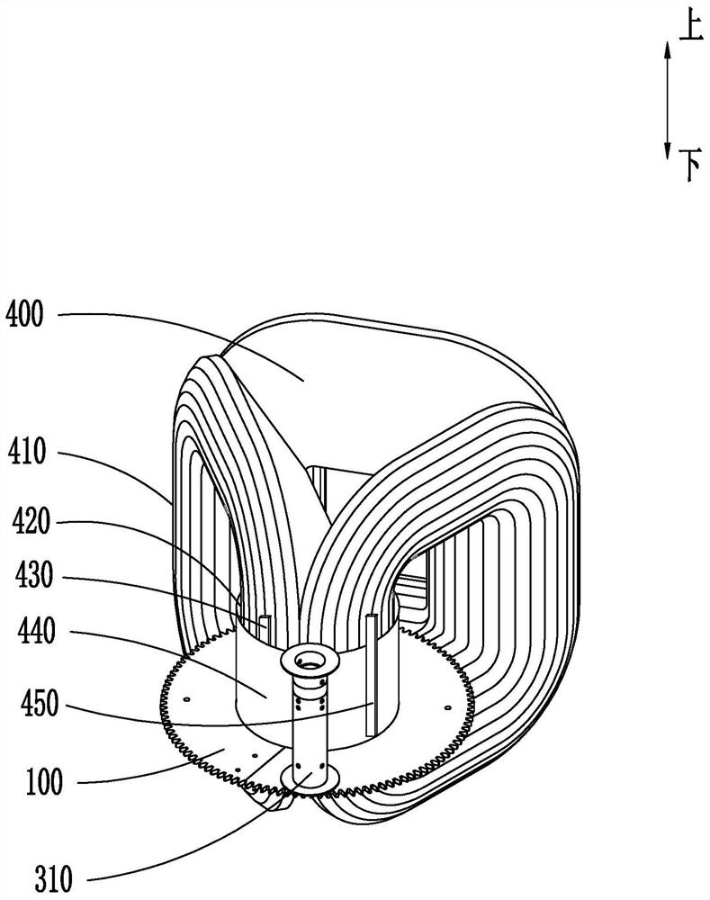
The invention discloses a foil coil winding method and device for a three-dimensional wound core transformer. The device comprises a rotating assembly, a driving device and a plurality of feeding assemblies. A through hole matched with an iron core column is formed in the rotating assembly, the rotating assembly is provided with a gear plate and a track ring around the through hole, and the gear plate and the track ring are fixedly connected through a fixing block; the feeding assembly comprises a charging barrel and a tension device, and the charging barrel is movably connected with the rotating assembly; the driving end of the driving device is connected with the gear plate. According to the foil coil winding device for the three-dimensional wound core transformer, through the rotating assembly and the feeding assembly, a winding material wound on a charging barrel can be stably and rapidly conveyed outwards along with rotation of a gear plate, and the feeding stability and the winding efficiency of the foil coil winding device for the three-dimensional wound core transformer are improved; by arranging the track ring and the tension device, the conditions of displacement and dislocation of the charging barrel in the rotating process are avoided, the coil quality is guaranteed, and the automation degree of foil coil winding of the three-dimensional wound core transformer is improved.

Description

technical field [0001] The invention relates to the technical field of transformer production, in particular to a foil coil winding method and device for a three-dimensional wound core transformer. Background technique [0002] The three-dimensional wound core transformer is an energy-saving power transformer, which creatively reforms the laminated magnetic circuit structure and three-phase layout of the traditional power transformer, making the product performance more optimized. Due to the structural characteristics of the three-dimensional wound core, it is impossible to use the winding package method similar to the laminated core structure (that is, the production process of putting the coil into the core after the coil is wound), and the three-dimensional wound core must be customized according to different products. The winding equipment winds the winding on the core. The current common three-dimensional wound core foil winding method is to customize the winding equip...

Claims


Application Information

Patent Timeline
Patent Type & Authority Applications(China)
IPC IPC(8): H01F41/06H01F41/096H01F41/094
CPCH01F41/06H01F41/096H01F41/061
Inventor 许凯旋梁庆宁司徒树伟戚宇祥宋丹菊方文杰李飞张学明周宇成方文惠翟丽珍
Owner HAIHONG ELECTRIC CO LTD
Why Eureka
Try Eureka