High-voltage cable joint protection device and method
A high-voltage cable and protection device technology, applied in the direction of cable joints, electrical components, etc., can solve the problems of inconvenient use, poor sealing of the protection box, and reduce the work efficiency of the staff, so as to ensure the sealing, easy to use, and strong practicability Effect
- Summary
- Abstract
- Description
- Claims
- Application Information
AI Technical Summary
Problems solved by technology
Method used
Image

Examples
Embodiment 1
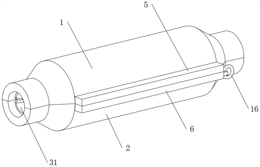
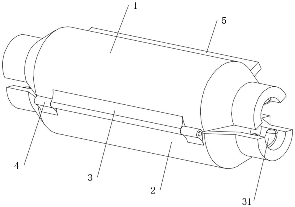
[0038] see Figure 1-9 , in an embodiment of the present invention, a high-voltage cable joint protection device includes an upper shell 1 and a lower shell 2, the lower end of the upper shell 1 is provided with a mounting head 3, and the upper end of the lower shell 2 One side is provided with mounting seats 4 located on both sides of the mounting head 3, and the mounting head 3 is rotationally connected with the mounting seats 4;
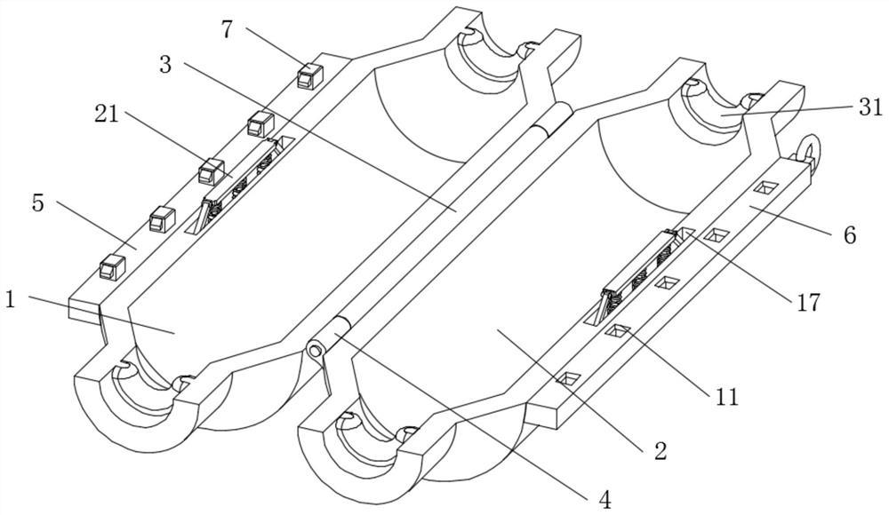
[0039]The upper casing 1 and the lower casing 2 are provided with an installation assembly and a disassembly assembly that facilitate the disassembly of the upper casing 1 and the lower casing 2. The installation assembly includes a bottom end of the upper casing 1 away from the installation head 3 side of the upper mounting plate 5, the upper end of the lower housing 2 is provided with a lower mounting plate 6 corresponding to the upper mounting plate 5, and the lower end of the upper mounting plate 5 is equidistantly provided with a number of li...
Embodiment 2
[0048] The difference from Embodiment 1 is that hydraulic oil is provided in the cavity 27, so that the fixed plate 28 can move more evenly and stably, ensuring the stability of the device, and the hydraulic oil can make the device self-sustaining. Lubrication enhances the life of the unit.
[0049] The working principle of the present invention is: when using the device, the cable connector is first placed between the upper casing 1 and the lower casing 2, then the upper casing 1 is rotated to cover the lower casing 2, and at the same time the When housing 1, the limit block 7 will retract and move into the card slot 11, and the lower mounting plate 6 will squeeze the block 9 to retract into the limit slot 8 at the same time, when the limit block 7 is completely put into the card slot After entering the groove 11, the block 9 will pop out and be stuck in the chute 12 through the rebound of the first spring 10, and the upper casing 1 and the lower casing 2 will be fixedly inst...
PUM
 Abstract
Description
Claims
Application Information
 - Generate Ideas
- Intellectual Property
- Life Sciences
- Materials
- Tech Scout
- Unparalleled Data Quality
- Higher Quality Content
- 60% Fewer Hallucinations
Browse by: Latest US Patents, China's latest patents, Technical Efficacy Thesaurus, Application Domain, Technology Topic, Popular Technical Reports.
© 2025 PatSnap. All rights reserved.Legal|Privacy policy|Modern Slavery Act Transparency Statement|Sitemap|About US| Contact US: help@patsnap.com