
Internet-of-things intelligent stamping equipment

An intelligent and IoT technology, applied in TV, printing, stamping, etc., can solve problems such as discrepancies and inability to guarantee the accuracy of contract content.

Active Publication Date: 2021-09-03
江苏群杰物联科技有限公司
View PDF10 Cites 2 Cited by
  • Summary
  • Abstract
  • Description
  • Claims
  • Application Information

AI Technical Summary

Problems solved by technology

[0004] However, in the actual stamping process, just shooting the content through a fixed camera is far from being able to guarantee the accuracy of the contract content. Once the seal custodian colludes with the other party, the contract may be replaced after the approver verifies the content. Part of the text in the contract is replaced, which can easily cause differences between the covered document and the actual audit document, and there are huge loopholes

Method used


Image

  • Internet-of-things intelligent stamping equipment
  • Internet-of-things intelligent stamping equipment
  • Internet-of-things intelligent stamping equipment

Examples


Embodiment 1

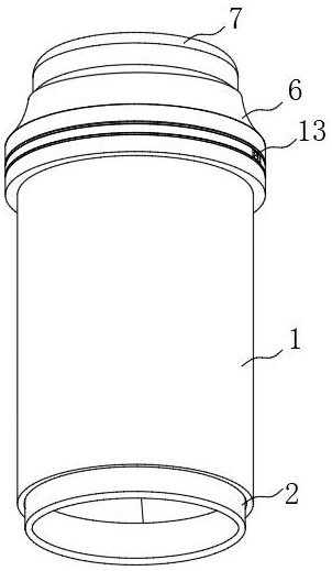
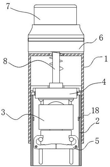
[0046] see Figure 1-Figure 4 , in an embodiment of the present invention, an IoT smart stamping device, comprising:

[0047] An outer cylinder 1, an inner cylinder 2 is arranged inside the outer cylinder 1;

[0048] The stamp part 3 is arranged inside the inner tube 2 and slides along the extension direction of the inner tube 2. The stamp part 3 contains the core components required for the entire stamping process, which at least includes a chapter head, a paint box, a stamp holder, etc. Components, which can be composed of the header part of the traditional flip-type stamp, which has been relatively mature in the prior art, so it will not be described in detail here;

[0049]The locking mechanism 4 is arranged inside the inner cylinder 2, and the locking mechanism 4 is located above the seal part 3 and connected with the seal part 3 for locking the seal part 3;

[0050] The baffle 5 is rotatably arranged inside the inner cylinder 2. The baffle 5 is located below the seal p...

Embodiment 2

[0073] see Figure 10 , Figure 11 , the present embodiment is compared to embodiment 1, one of the differences is:

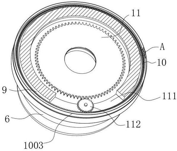
[0074]The drive module 11 is different. In the embodiment of the present invention, the drive module 11 includes a mounting groove 1101 provided inside the pressing cylinder 6. The mounting groove 1101 communicates with the annular groove 9. A micromotor 1102 is fixedly installed inside the mounting groove 1101. The output shaft of the micromotor 1102 is fixedly connected with the first gear 1103, and the first gear 1103 meshes with the ring gear 1002. During the stamping process, the stamper places the stamp at the position to be stamped, and then starts the micromotor 1102, Drive the first gear 1103 to rotate, the rotation of the first gear 1103 drives the ring gear 1002 to rotate, and the ring gear 1002 drives the ring mount 1001 to rotate. During this process, the camera 1301 rotates. During the rotation, the content of the contract and the seal will be st...


PUM


Abstract

The invention discloses an internet-of-things intelligent stamping device, and belongs to the technical field of intelligent stamps, and the technical scheme is characterized in that the internet-of-things intelligent stamping device comprises a rotating module arranged in an annular groove, wherein the rotating module can rotate along the annular groove; a driving module arranged in the pressing cylinder, matched with the rotating module and used for driving the rotating module to rotate; a camera module arranged on the rotating module; and a power supply module arranged in the pressing cylinder and used for supplying power to the driving module and the camera module, wherein the driving module drives the rotating module to rotate so as to drive the camera module to do circular motion, the camera module rotates and is used for taking pictures of the stamped content in all directions, the stamped content is prevented from being replaced by people after being shot, the legality of the stamped content is further guaranteed, and compared with a traditional single-camera type stamp, the use effect is better.

Description

technical field [0001] The invention relates to the technical field of smart seals, and more specifically, to an IoT smart stamping device. Background technique [0002] The current seals are generally designated to be kept by special personnel, but due to personnel negligence or favoritism of the custodians, theft of seals often occurs, especially when the approver is not at the scene of stamping, theft is more likely to occur. [0003] Based on the above-mentioned problems, some smart seals have begun to appear on the market. Among them, see the patent named "Smart Seal" with the publication number CN 110406277 B. The verification device can be transmitted to the approver's mobile phone through the information collection and transmission unit, and the content and chapter header can be checked to ensure that the seal is correct and avoid the phenomenon of false stamps." It can check the content through the camera. [0004] However, in the actual stamping process, just shoo...

Claims


Application Information

Patent Timeline
Patent Type & Authority Applications(China)
IPC IPC(8): H04N5/232H04N7/18B41K1/02B41K1/36
CPCH04N7/18B41K1/02B41K1/36H04N23/617H04N23/695
Inventor 朱杰陈朕孔德伟郭鑫
Owner 江苏群杰物联科技有限公司
Learn More