Breast surgery biopsy sample storage box

A breast surgery and storage box technology, applied in the field of storage boxes, can solve the problems that the cover cannot be fixed, broken, and affect the use of the storage box, etc.

Pending Publication Date: 2021-09-07
郭军峰
View PDF5 Cites 3 Cited by
  • Summary
  • Abstract
  • Description
  • Claims
  • Application Information

AI Technical Summary

Problems solved by technology

[0003] Most of the existing storage boxes for breast surgical biopsy samples only provide the function of placing biopsy sample test tubes, resulting in the test tubes being easily broken due to external impact during storage and transportation, and the safety of the test tubes cannot be well ensured. When the test tubes are taken out, The user needs to take it out repeatedly, which consumes more energy. Secondly, the cover plate cannot be fixed in one place during the turning and opening process, which affects the use of the storage box. At the same time, the cover plate of the storage box cannot be kept closed for a long time. The box falls out, and the test tube is placed in the storage, it is easy to shake and cause the test tube to break

Method used


Image

  • Breast surgery biopsy sample storage box
  • Breast surgery biopsy sample storage box
  • Breast surgery biopsy sample storage box

Examples


Embodiment 1

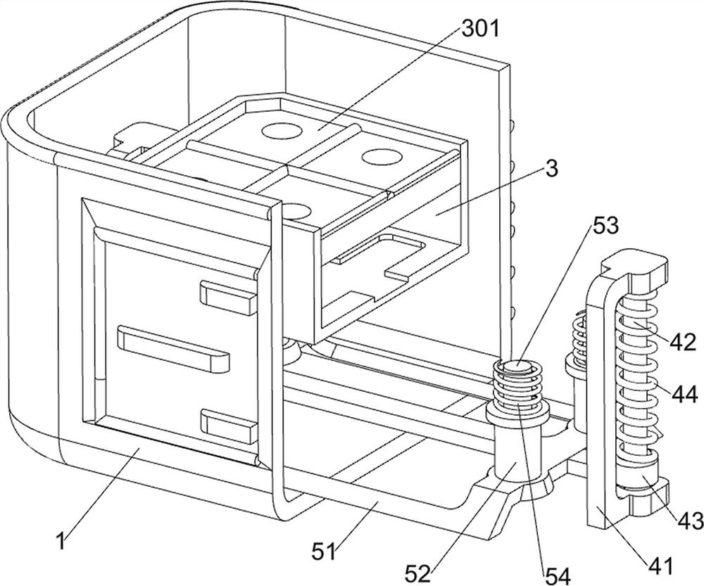
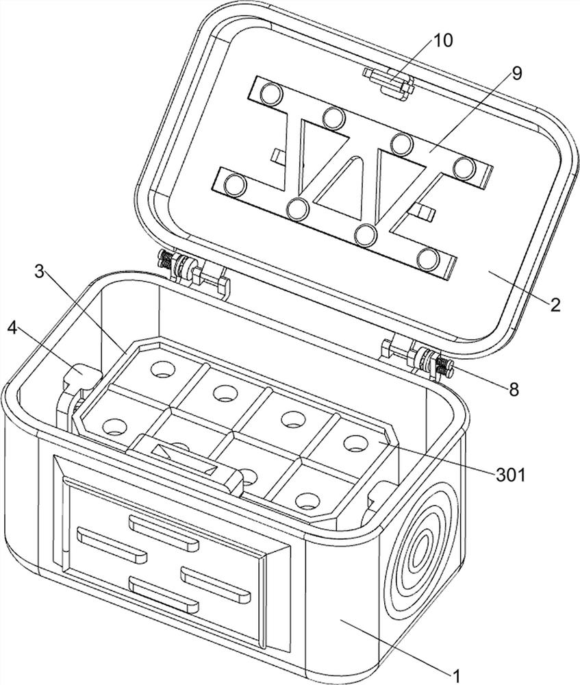
[0029] Such as Figure 1 to Figure 5 As shown, this embodiment discloses a biopsy sample storage box for breast surgery, which includes a box body 1, a cover plate 2, a placement frame 3, a first protective cotton board 301, a mounting mechanism 4, a shock absorbing mechanism 5 and a locking mechanism 6 , the upper rear side of the box body 1 is rotatably connected with a cover plate 2, the lower part of the box body 1 is provided with a mounting mechanism 4, the mounting mechanism 4 is provided with a shock absorbing mechanism 5, and the shock absorbing mechanism 5 is provided with a placement frame 3, and the placement frame 3. A first protective cotton board 301 is connected to the inner upper part, and a locking mechanism 6 is provided between the placement frame 3, the inner lower side of the box body 1 and the shock-absorbing mechanism 5.

[0030] The mounting mechanism 4 includes a fixed mount 41, a fixed rod 42, a slide block 43 and a return spring 44. The lower side o...

Embodiment 2

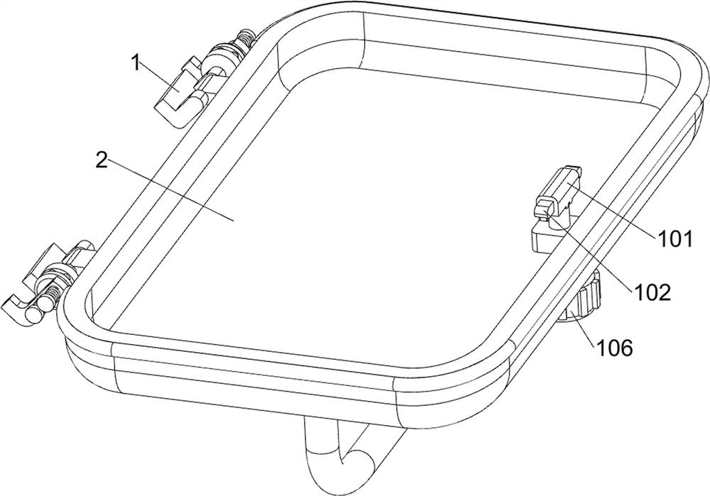
[0036] Such as figure 1 , figure 2 , Figure 6 ~ Figure 10 As shown, in some embodiments, a positioning assembly 8 is also included. The positioning assembly 8 includes a positioning convex plate 81, a mounting block 82, a sliding shaft 83, a positioning concave plate 84 and a first spring 85. The outer side of the cover plate 2 transmission shaft Both are connected with positioning convex discs 81, and the rear side of the upper part of the box body 1 is symmetrically connected with mounting blocks 82. The upper part of the mounting blocks 82 is connected with sliding shafts 83 symmetrically up and down, and the sliding shafts 83 and the mounting blocks 82 are connected symmetrically up and down. There is a first spring 85, and the first spring 85 is sleeved on the sliding shaft 83, and the inner side of the sliding shaft 83 is connected with a positioning concave disk 84, and the positioning concave disk 84 cooperates with the positioning convex disk 81.

[0037] When the...


PUM


Abstract

The invention discloses a breast surgery biopsy sample storage box, which comprises a box body and the like, wherein, a cover plate is rotatably connected to the rear side of the upper part of the box body, an installation mechanism is arranged at the lower part in the box body, a damping mechanism is arranged on the installation mechanism, a placing frame is arranged on the damping mechanism, and a first protective cotton plate is connected to the upper part of the inner side of the placing frame. The breast surgery biopsy sample storage box disclosed by the invention has the advantages that the cover plate is rotatably positioned, biopsy sample test tubes are automatically pressed and fixed, random shaking of the test tubes is avoided, and the cover plate is conveniently fixed to keep the box body closed.

Description

technical field [0001] The invention relates to a storage box, in particular to a storage box for breast surgical biopsy samples. Background technique [0002] Breast biopsy is the abbreviation of "breast biopsy pathological examination", which refers to the method of using local excision, forceps, puncture needle suction, scratching, extirpation and other surgical methods to take pathological examination of diseased tissue from the patient's living body to confirm the diagnosis. The resulting biopsy samples need to be kept properly. [0003] Most of the existing storage boxes for breast surgical biopsy samples only provide the function of placing biopsy sample test tubes, resulting in the test tubes being easily broken due to external impact during storage and transportation, and the safety of the test tubes cannot be well ensured. When the test tubes are taken out, The user needs to take it out repeatedly, which consumes more energy. Secondly, the cover plate cannot be fi...

Claims


Application Information

Patent Timeline
Patent Type & Authority Applications(China)
IPC IPC(8): A61B10/02
CPCA61B10/02A61B10/0096
Inventor 郭军峰
Owner 郭军峰
Why Eureka
Try Eureka