Flue gas filtering device
A filter device and flue gas technology, applied in the directions of dispersed particle filtration, separation method, dispersed particle separation, etc., can solve the problems of falling on the filter bag, inconvenient use, clogging of the filter bag, etc., to prevent agglomeration, improve the use of Longevity, the effect of avoiding clogging
- Summary
- Abstract
- Description
- Claims
- Application Information
AI Technical Summary
Problems solved by technology
Method used
Image

Examples
Embodiment 1
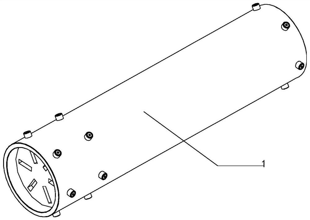
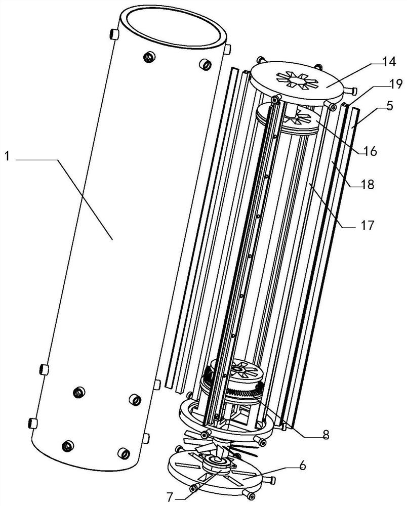
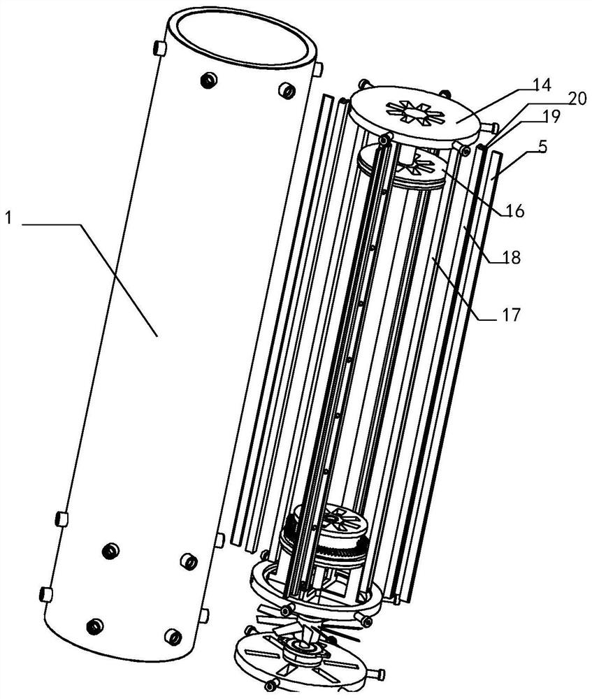
[0034] Such as figure 1 , figure 2 , Figure 4 with Figure 9 As shown, a flue gas filtering device proposed in this embodiment is suitable for use in thermal power plants, including: a flue gas pipe 1, a mounting frame 2, a mounting plate 6, and a linkage assembly 8, and the mounting frame 2 is installed on the flue gas pipe 1 On the inner wall, a rotating disk 3 coaxial with the flue gas pipe 1 is rotated above the mounting bracket 2, and a mounting block 4 is installed on the circumferential side of the rotating disk 3, and a scraper for cleaning the inner wall of the flue gas pipe 1 is installed on the mounting block 4 5. The mounting plate 6 is installed on the inner wall of the flue gas pipe 1 and is located in the direction of the mounting frame 2 away from the scraper 5. The motor 7 is installed on the mounting plate 6, and the linkage assembly 8 is mounted on the mounting frame 2 and acts on the rotating disk 3. , the output shaft of the motor 7 is connected with ...
PUM
 Abstract
Description
Claims
Application Information
PatSnap Eureka turns technology decisions into work you can execute. Powered by our Innovation Knowledge Graph, it runs expert workflows across engineering, life sciences, materials and intellectual property. Get your review-ready output in minutes.


