
Oil reservoir protector and application of oil reservoir protector in risk well of oil production engineering

A technology of protector and oil layer, which is applied in the direction of wellbore/well valve device, drilling equipment, earthwork drilling and production, etc., and can solve problems such as blowout, economic loss, and environmental pollution

Pending Publication Date: 2021-09-07
徐瑞祥
View PDF0 Cites 1 Cited by
  • Summary
  • Abstract
  • Description
  • Claims
  • Application Information

AI Technical Summary

Problems solved by technology

[0002] When the oil pump is used in the oil field to produce oil, operations such as lifting and lowering the oil pipe, inspecting the pump, and replacing the sucker rod are required during the operation. This will bring the liquid inside the oil pipe to the ground, pollute the environment, and may cause a blowout in severe cases, affecting production. and operations bring safety hazards, resulting in economic losses

Method used


Image

  • Oil reservoir protector and application of oil reservoir protector in risk well of oil production engineering

Examples


Embodiment

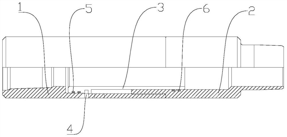
[0031] Please refer to figure 1 shown. This embodiment provides an oil layer protector, which includes an upper joint 1, a constant pressure sliding sleeve 3 and a lower joint 2. The upper joint 1 and the lower joint 2 are connected to form a cavity, and the constant pressure sliding sleeve 3 is located in the cavity. The upper joint 1 is provided with a first oil drain through hole for communicating with the cavity, the lower joint 2 is provided with a second oil drain through hole for communicating with the cavity, and the upper joint 1 is provided with a hole for the constant pressure sliding sleeve 3 to discharge the first oil drain The stopper for blocking the oil through hole and the second oil drain through hole.

[0032]In the above embodiment, an oil layer protector is composed of an upper joint 1, a constant pressure sliding sleeve 3 and a lower joint 2, wherein the upper joint 1 and the lower joint 2 are connected to form a cavity, and the constant pressure sliding...


PUM


Abstract

The invention provides an oil reservoir protector and application of the oil reservoir protector in a risk well of oil production engineering, and relates to the technical field of oil exploitation. According to the scheme, the oil reservoir protector comprises an upper connector, a constant-pressure sliding sleeve and a lower connector, a cavity is formed after the upper connector and the lower connector are connected, the constant-pressure sliding sleeve is located in the cavity, the upper connector is provided with a first oil drainage through hole used for being communicated with the cavity, and the lower connector is provided with a second oil drainage through hole used for being communicated with the cavity; and the upper connector is provided with a limiting piece used for enabling the constant-pressure sliding sleeve to block the first oil drainage through hole and the second oil drainage through hole. By means of the oil reservoir protector, on one hand, risk delay can be avoided, blowout is prevented, and meanwhile, the oil drainage function of a normal oil well is achieved; and on the other hand, the oil layer protector is applied to oil production engineering operation, so that a wellhead can be kept clean, and the environment is protected.

Description

technical field [0001] The invention relates to the technical field of petroleum exploitation, in particular to an oil layer protector and its application. Background technique [0002] When the oil pump is used in the oil field to produce oil, operations such as lifting and lowering the oil pipe, inspecting the pump, and replacing the sucker rod are required during the operation. This will bring the liquid inside the oil pipe to the ground, pollute the environment, and may cause a blowout in severe cases, affecting production. and operations bring safety hazards and cause economic losses. [0003] At present, the traditional protection methods include pull rod oil drainer, striker oil drainer and other tools. Among them, the pull rod type oil drain is used in inclined wells, and the switch of horizontal wells is affected by the well conditions, and the switch is not controlled. Hirai, the force of gravity on the tool when opened is out of control. Contents of the inventi...

Claims


Application Information

Patent Timeline
Patent Type & Authority Applications(China)
IPC IPC(8): E21B34/08E21B17/042
CPCE21B34/08E21B17/042
Inventor 徐瑞祥
Owner 徐瑞祥
Learn More