
Leakage detection device and leakage detection method for gas between main and auxiliary fuel gas solenoid valves

A main solenoid valve and solenoid valve technology, which can be used in measuring devices, fluid tightness testing, and measurement of fluid acceleration and deceleration rates, etc., can solve problems such as gas leakage, occupying maintenance time, explosion, etc., and achieve easy maintenance and disassembly. Convenience and accurate data

Pending Publication Date: 2021-09-07
深圳市联兴泰软件技术有限公司
View PDF0 Cites 0 Cited by
  • Summary
  • Abstract
  • Description
  • Claims
  • Application Information

AI Technical Summary

Problems solved by technology

One is that this method belongs to one-way control. It only adds a solenoid valve backup to ensure the safety of the gas switch. The system does not introduce solenoid valve control status feedback. If a solenoid valve is damaged and cannot be closed during use, the system cannot check it. from
In an extreme environment, once two solenoid valves are damaged at the same time, resulting in gas leakage, it will cause immeasurable losses such as explosion
The second is that this method is not conducive to the maintenance of equipment at ordinary times. During equipment maintenance, maintenance personnel can only test the on-off status of the main and auxiliary solenoid valves to judge whether the solenoid valves are working normally. This requires a lot of maintenance time and increases equipment maintenance costs.

Method used


Image

  • Leakage detection device and leakage detection method for gas between main and auxiliary fuel gas solenoid valves
  • Leakage detection device and leakage detection method for gas between main and auxiliary fuel gas solenoid valves
  • Leakage detection device and leakage detection method for gas between main and auxiliary fuel gas solenoid valves

Examples


Embodiment Construction

[0041] The following will clearly and completely describe the technical solutions in the embodiments of the present invention with reference to the accompanying drawings in the embodiments of the present invention. Obviously, the described embodiments are only some, not all, embodiments of the present invention. Based on the embodiments of the present invention, all other embodiments obtained by persons of ordinary skill in the art without making creative efforts belong to the protection scope of the present invention.

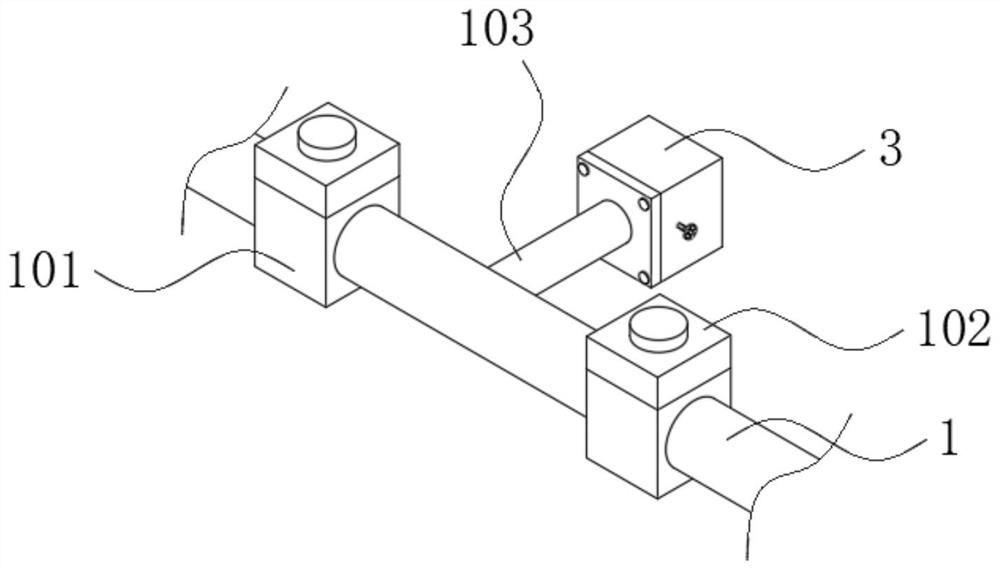
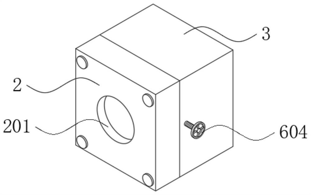
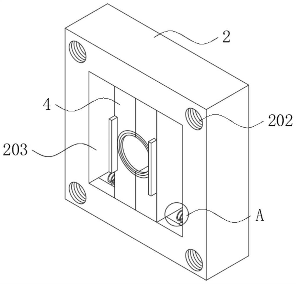
[0042] see Figure 1-10 As shown, a gas leak detection device between main and auxiliary solenoid valves of gas comprises:

[0043] Gas pipeline 1, a main solenoid valve 101 and a secondary solenoid valve 102 are respectively arranged on the pipe wall of the gas pipeline 1, and a detection pipeline 103 is arranged between the main solenoid valve 101 and the secondary solenoid valve 102 on the pipe wall of the gas pipeline 1;

[0044] The detection pipeline 103 ...


PUM


Abstract

The invention discloses a leak detection device and leak detection method for gas between main and auxiliary fuel gas solenoid valves. The leak detection device comprises a fuel gas pipeline, a protection box, a pipe clamping assembly and a fixing plate, wherein the main solenoid valve and the auxiliary solenoid valve are respectively arranged on the pipe wall of the fuel gas pipeline, and a detection pipeline is arranged on the pipe wall of the fuel gas pipeline and between the main solenoid valve and the auxiliary solenoid valve; the protection box is connected with one end of the detection pipeline in a penetrating manner; a packaging cover is arranged on the front surface of the protection box. The pipe clamping assembly is arranged in the packaging cover; the fixing plate is arranged in the protection box, a pressure sensor is arranged at the top end of the fixing plate, and a sealing assembly is arranged at the top end of the fixing plate and located on the front face of the pressure sensor. The leak detection device has the beneficial effects that the gas pressure sensor is additionally arranged between the main electromagnetic valve and the auxiliary electromagnetic valve, whether the main electromagnetic valve and the auxiliary electromagnetic valve leak gas or are damaged or not can be conveniently judged according to the gas pressure change condition between the main electromagnetic valve and the auxiliary electromagnetic valve, locking is conducted in time, and an alarm is given to prompt a user.

Description

technical field [0001] The invention relates to a gas leak detection device and a leak detection method, in particular to a gas leak detection device and a leak detection method between main and auxiliary solenoid valves of gas, and belongs to the technical field of gas detection. Background technique [0002] Gas burners are widely used in boilers and industrial combustion and other fields that require heating applications. They are special equipment products and have high safety requirements. At present, a main switch solenoid valve and a secondary switch solenoid valve are generally connected in series in the gas burner intake pipe. When working, the gas can enter the combustion chamber only when the two solenoid valves are turned on at the same time, so as to ensure the safety of the switch control of the gas pipeline. [0003] In practical application, this method has two disadvantages. One is that this method belongs to one-way control. It only adds a solenoid valve ...

Claims


Application Information

Patent Timeline
Patent Type & Authority Applications(China)
IPC IPC(8): G01M3/28
CPCG01M3/2876G01M3/2815
Inventor 刘兴元
Owner 深圳市联兴泰软件技术有限公司
Learn More