Connecting piece special for loading and unloading of municipal road garbage truck and using method
A municipal road and special connection technology, which is applied in the direction of garbage receptacle, transportation and packaging, etc., can solve the problems of complex layout, unfavorable cost saving and efficient operation in the field of special vehicles, and high assembly cost
- Summary
- Abstract
- Description
- Claims
- Application Information
AI Technical Summary
Problems solved by technology
Method used
Image
Examples
Embodiment 1
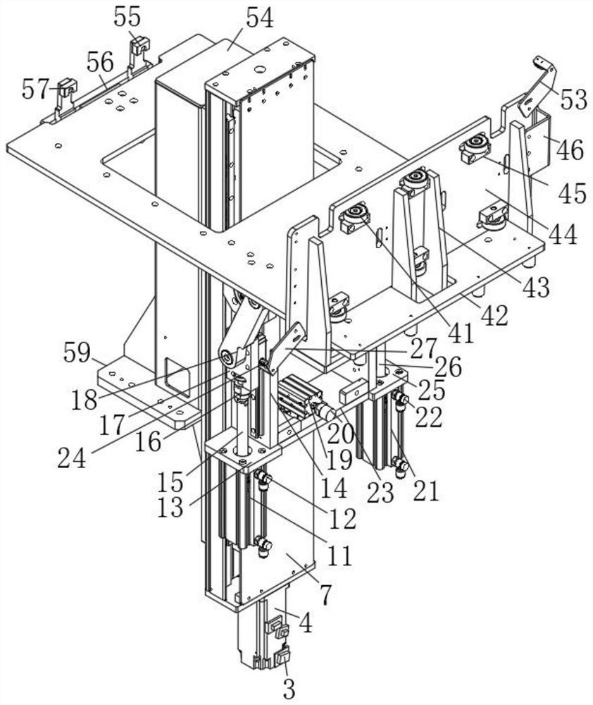
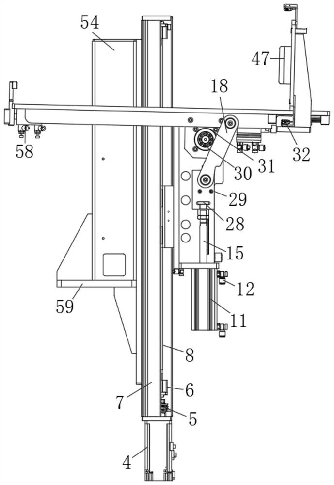
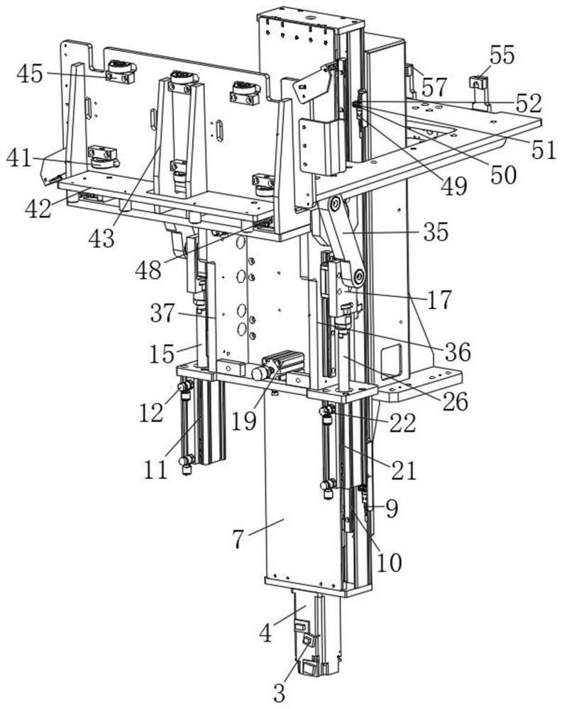
[0034] Such as Figure 1-8 As shown, the special connectors for loading and unloading municipal road garbage trucks include a machine plate 1, a machine connecting block 3, a machine center 5, a rotating head 6, a connecting line 9, a first support plate 13, a first vertical support plate 14, a fixed Bolt 16, connecting groove plate 17 and movable rod 20, one end of the machine plate 1 is provided with a second rolling servo rod 2, one end of the second rolling servo rod 2 is provided with an organic connecting block 3, and one end of the mechanical connecting block 3 is provided with a servo motor 4. One end of the servo motor 4 is provided with an organic center 5, one end of the machine center 5 is provided with a rotating head 6, one end of the rotating head 6 is provided with an organic outer plate 7, and one end of the outer plate 7 is provided with a first rolling servo rod 8, the second One end of a rolling servo rod 8 is provided with a connecting line 9, and one end ...
Embodiment 2
[0043] The method of using the special connector for loading and unloading municipal road garbage trucks, the steps of the method are as follows:
[0044] Step 1: The rotation of the servo motor 4 further drives the rotation of the machine center 5 inside the machine outer plate 7, the rotation of the machine center 5 further drives the rotation of the rotor 6, and the rotation of the rotor 6 further drives the first rolling servo lever 8 and The rotation of the second rolling servo lever 2;
[0045] Step 2: Through the rotation of the first rolling servo lever 8 and the second rolling servo lever 2, the bottom support plate 42 is pushed forward, and the first rolling servo lever 8 and the second rolling servo lever 2 are in the process of pushing the bottom support plate 42 During the process of rotation of the first hydraulic cylinder 11 and the second hydraulic cylinder 21, the rotation of the first hydraulic cylinder 11 and the second hydraulic cylinder 21 further drives t...
Embodiment 3
[0051] Working principle: the rotation of the servo motor 4 further drives the rotation of the machine center 5 inside the machine outer plate 7, the rotation of the machine center 5 further drives the rotation of the rotor 6, and the rotation of the rotor 6 further moves the first rolling servo lever 8 and The rotation of the second rolling servo lever 2, through the rotation of the first rolling servo lever 8 and the second rolling servo lever 2, and then pushes the bottom support plate 42 forward, the first rolling servo lever 8 and the second rolling servo lever 2 are pushing During the process of the bottom support plate 42, it further drives the rotation of the first hydraulic cylinder 11 and the second hydraulic cylinder 21, and in the process of the rotation of the first hydraulic cylinder 11 and the second hydraulic cylinder 21, it further drives the first hydraulic rod 15 and the second hydraulic cylinder. The forward push of the two hydraulic rods 26, through the for...
PUM
 Abstract
Description
Claims
Application Information
 - R&D
- Intellectual Property
- Life Sciences
- Materials
- Tech Scout
- Unparalleled Data Quality
- Higher Quality Content
- 60% Fewer Hallucinations
Browse by: Latest US Patents, China's latest patents, Technical Efficacy Thesaurus, Application Domain, Technology Topic, Popular Technical Reports.
© 2025 PatSnap. All rights reserved.Legal|Privacy policy|Modern Slavery Act Transparency Statement|Sitemap|About US| Contact US: help@patsnap.com


