Stacking device and stacking system for stacking packaging box bodies
A stacking device and packaging technology, which is applied in the field of air-conditioning outdoor unit stacking, can solve problems such as large safety hazards, falling packaging boxes, and product damage.
- Summary
- Abstract
- Description
- Claims
- Application Information
AI Technical Summary
Problems solved by technology
Method used
Image

Examples
Embodiment 1
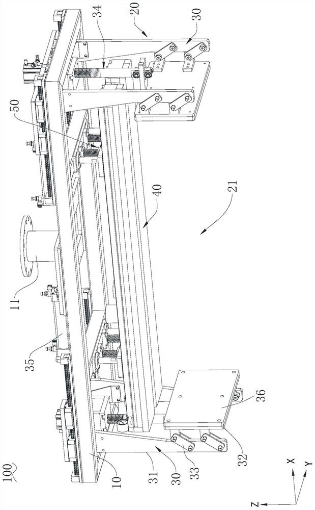
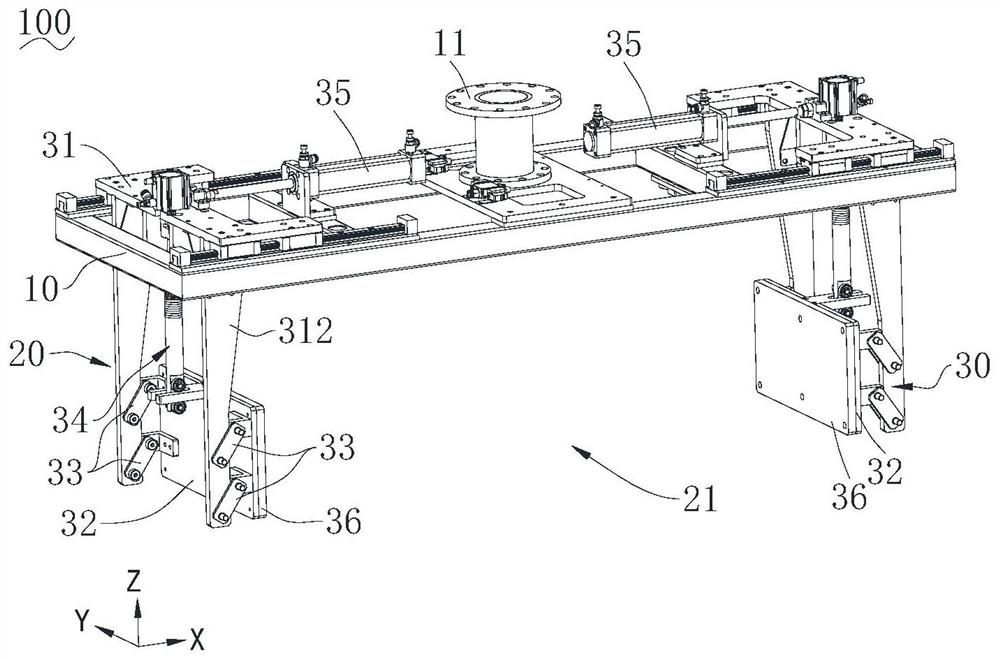
[0047] Such as Figure 1 to Figure 13 As shown, the palletizing device 100 provided in this embodiment is used for the handling of the packaging box 200, which includes a mounting frame 10, a clamping device 20 and a sponge suction cup 40, through which the clamping device 20 and the The sponge suction cup 40 is used to fix the packaging box 200 so that the packaging box 200 can move together with the installation frame 10 . It should be noted that the above-mentioned palletizing device 100 can also only install the clamping device 20, and clamp and loosen the packaging box 200 by the clamping device 20 to clamp and loosen the packaging box 200; or Only the sponge suction cup 40 is installed, and the suction and release of the packaging box body 200 are realized by the sponge suction cup 40 sucking and loosening the packaging box body 200 . Of course, the clamping device 20 and the sponge suction cup 40 are installed at the same time, and the clamping device 20 and the sponge...
Embodiment 2
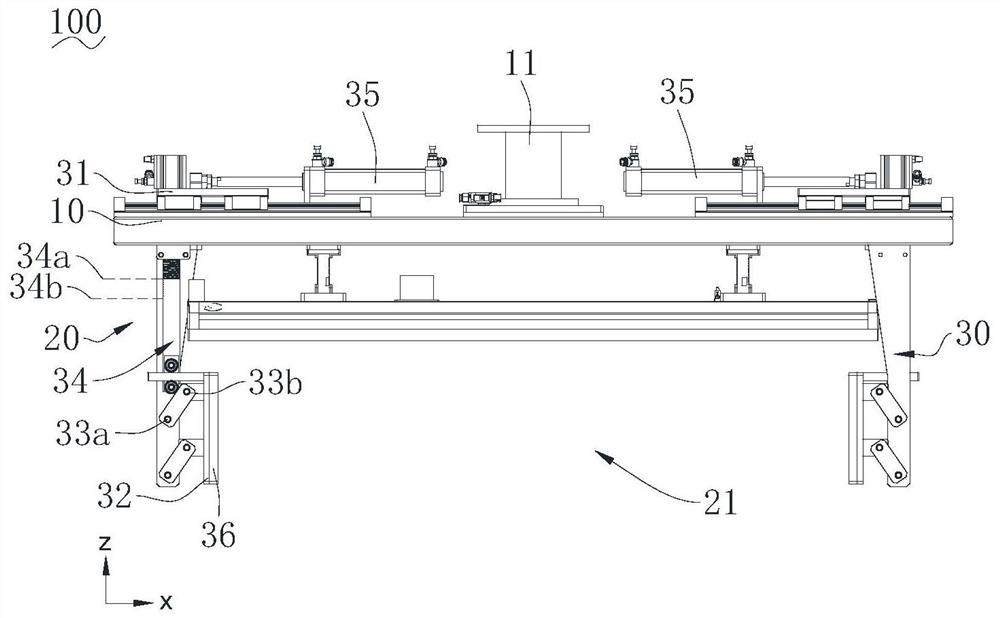
[0081] see Figure 14, the clamping mechanism 30 of the present embodiment, the clamping plate 32 is located between the two moving seats 31, and the maintaining drive member 343 is arranged on the bottom of the moving seats 31, wherein the first position 34a is located below the second position 34b, connected The rod 33 extends downward from the moving base 31 and obliquely toward the clamping space 21 to the clamping plate 32 . In this embodiment, the moving base 31 is installed on the mounting frame 10 through a slider, and the driving member 343 is fixedly installed on the bottom of the moving base 31, and its output shaft protrudes upwards and is connected with the bottom of the operating rod 341 to maintain the drive. The output shaft of the member 343 is substantially coaxial with the operating rod 341, and the elastic member 342 is but not limited to a compression spring. The operating rod 341 is flexibly connected to the clamping plate 32. Under the drive of the main...
Embodiment 3
[0084] see Figure 15 , the clamping mechanism 30 of the present embodiment, the clamping plate 32 is located on the outer side of the two moving seats 31, and the maintaining driver 343 is arranged on the top of the moving seats 31, wherein, the first position 34a is located above the second position 34b, connected The rod 33 extends obliquely downward and outward (direction away from the clamping space 21 ) from the moving seat 31 to the clamping plate 32 . In this embodiment, the moving base 31 is installed on the mounting frame 10 through a slider, and the driving member 343 is fixedly installed on the top of the moving base 31, and its output shaft protrudes downwards and is connected with the top of the operating rod 341 to maintain the drive. The output shaft of the member 343 is substantially coaxial with the operating rod 341, and the elastic member 342 is but not limited to a compression spring. The operating rod 341 is flexibly connected to the clamping plate 32. U...
PUM
 Abstract
Description
Claims
Application Information
 - R&D
- Intellectual Property
- Life Sciences
- Materials
- Tech Scout
- Unparalleled Data Quality
- Higher Quality Content
- 60% Fewer Hallucinations
Browse by: Latest US Patents, China's latest patents, Technical Efficacy Thesaurus, Application Domain, Technology Topic, Popular Technical Reports.
© 2025 PatSnap. All rights reserved.Legal|Privacy policy|Modern Slavery Act Transparency Statement|Sitemap|About US| Contact US: help@patsnap.com