Traction device capable of ensuring no burrs in electrostatic spinning

A traction device and electrospinning technology, applied in textiles and papermaking, filament/thread forming, fiber processing, etc., can solve the problems of reducing the beauty of finished fibers, inconvenient collection, and reducing work efficiency, etc.

Pending Publication Date: 2021-09-10
MINJIANG UNIV
View PDF8 Cites 0 Cited by
  • Summary
  • Abstract
  • Description
  • Claims
  • Application Information

AI Technical Summary

Problems solved by technology

[0003] However, when the traditional traction and winding device is used, it is found that due to the messy ejected fibers, there will be more burrs on both sides of the fibers wound on the winding roller. The messy burrs also reduce the aesthetics of the finished fiber. In addition, m...

Method used


Image

  • Traction device capable of ensuring no burrs in electrostatic spinning
  • Traction device capable of ensuring no burrs in electrostatic spinning
  • Traction device capable of ensuring no burrs in electrostatic spinning

Examples


no. 1 example

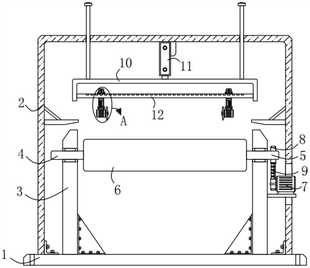
[0025] Please refer to Figure 1-Figure 3 , in the first embodiment of the present invention, the traction device capable of ensuring that electrospinning has no burrs includes: a base 1; a frame 2, which is fixedly installed on the top of the base 1; two supporting side plates 3. The two supporting side plates 3 are fixedly installed on the top of the base 1; the first connecting shaft 4 and the second connecting shaft 5, the first connecting shaft 4 and the second connecting shaft 5 are respectively rotatably installed on two On the support side plate 3; a winding roller 6, the winding roller 6 is arranged between the two support side plates 3; a motor 7, the motor 7 is fixedly installed on the shaft-4 away from the On the support side plate 3; two synchronous pulleys 8, the two synchronous pulleys 8 are respectively fixedly sleeved on the output shaft of the motor 7 and the second shaft 5; a synchronous belt 9, the synchronous belt 9 is set on the two synchronous pulleys 8...

no. 2 example

[0040] Based on the traction device provided by the first embodiment of the present application that can ensure no burr in electrospinning, the second embodiment of the present application proposes another traction device that can ensure burr-free electrospinning. The second embodiment is only a preferred mode of the first embodiment, and the implementation of the second embodiment will not affect the independent implementation of the first embodiment.

[0041] The second embodiment of the present invention will be further described below in conjunction with the drawings and implementation methods.

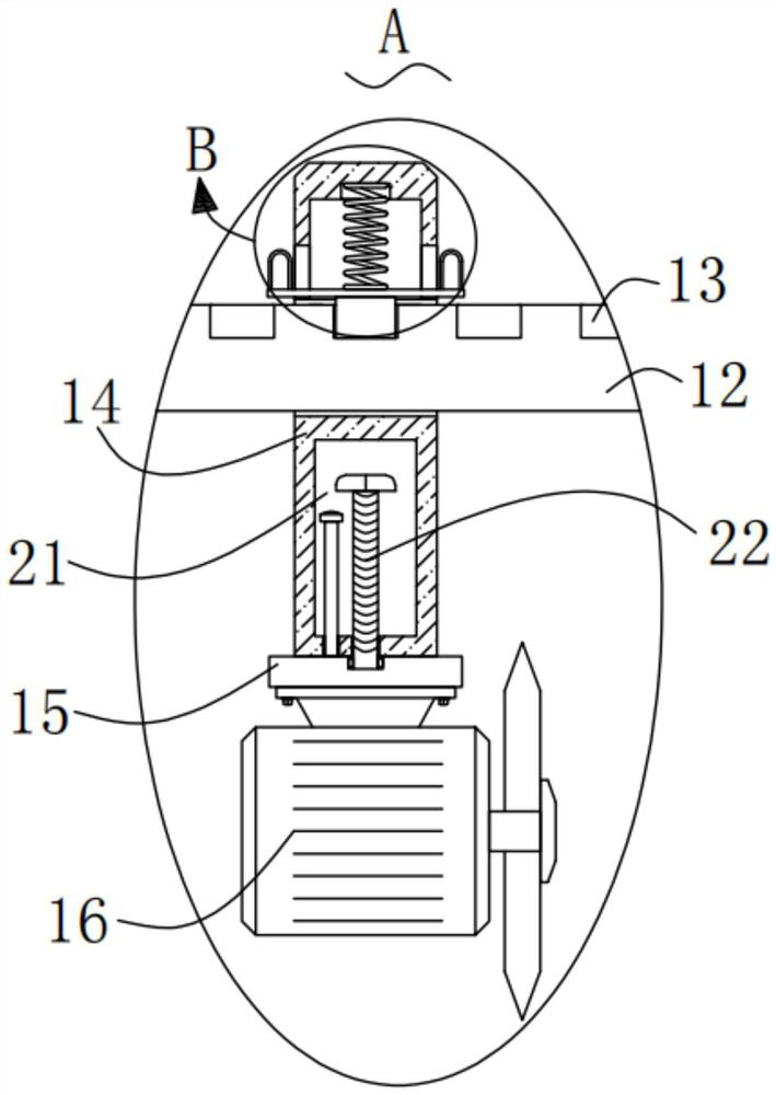
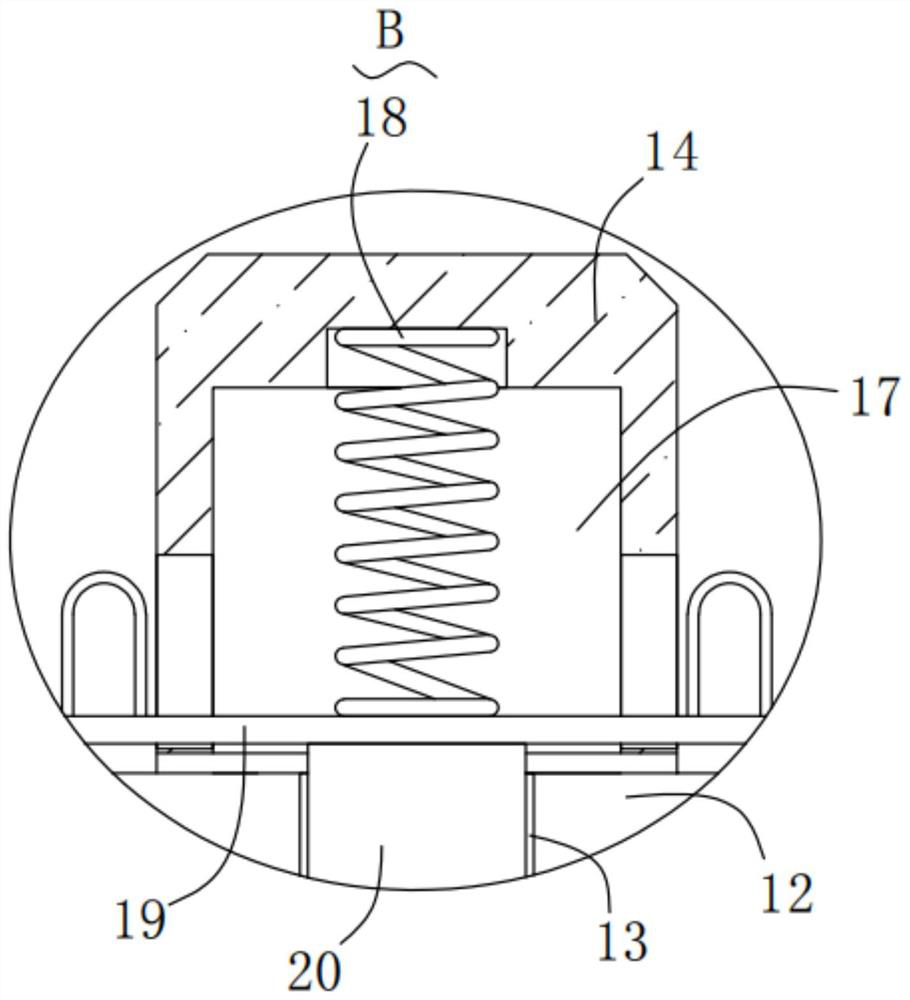
[0042] Please refer to Figure 4-Figure 5 , in the second embodiment of the traction device proposed by the present invention capable of ensuring no burrs in electrospinning: the ends of the connecting shaft 1 4 and the connecting shaft 2 5 that are close to each other are in contact with the winding roller 6, The connecting shaft 1 4 and the connecting shaft 2 5 are all provided...


PUM


Abstract

The invention provides a traction device capable of ensuring no burrs in electrostatic spinning. The traction device capable of ensuring no burrs in electrostatic spinning comprises a base; a frame I fixedly mounted at the top of the base; two supporting side plates both fixedly mounted at the top of the base; a connecting shaft I and a connecting shaft II rotationally mounted on the two supporting side plates respectively; a winding roller arranged between the two supporting side plates; a motor fixedly mounted on the supporting side plate far away from the connecting shaft I; and two synchronous belt wheels fixedly arranged on an output shaft of the motor and the connecting shaft II in a sleeving mode correspondingly. The traction device capable of ensuring no burrs in electrostatic spinning provided by the invention has the advantages that the burrs can be automatically cut off, people can conveniently collect fibers, a winding roller can be conveniently disassembled and assembled, and people can conveniently take materials.

Description

technical field [0001] The invention relates to the technical field of electrospinning, in particular to a traction device capable of ensuring no burrs in electrospinning. Background technique [0002] Electrospinning is a special form of electrostatic atomization of polymer fluids. At this time, the material split by atomization is not tiny droplets, but tiny jets of polymers, which can run for a long distance and finally solidify into fibers. Electrospinning is A special fiber manufacturing process, the polymer solution or melt is jet-spun in a strong electric field. In the electrospinning process, a winding roller is generally placed in front of the spinning, and the winding roller acts as a traction The function of winding can wind the ejected fibers, so that the ejected messy fibers can be wound and formed in an orderly manner, which is convenient for people to collect. [0003] However, when the traditional traction and winding device is used, it is found that due to ...

Claims


Application Information

Patent Timeline
IPC IPC(8): D01D5/00
CPCD01D5/0076
Inventor 柯惠珍魏取福
Owner MINJIANG UNIV
Why Eureka
Try Eureka