Supercharge Your Innovation With Domain-Expert AI Agents!

Damping expansion joint based on steel wire rope damper

A steel wire rope and damper technology, which is applied to bridge parts, bridge materials, bridges, etc., can solve problems such as uneven seam width, simple structure and poor adaptability of modular expansion devices

Active Publication Date: 2021-09-10
武汉东九永环工程技术有限公司
View PDF5 Cites 0 Cited by
  • Summary
  • Abstract
  • Description
  • Claims
  • Application Information

AI Technical Summary

Problems solved by technology

[0005] The purpose of the present invention is to solve the problem that the existing modular telescopic device has a simple structure, does not have multi-directional displacement function, cannot achieve the effect of damping, energy dissipation and shock absorption, and has poor adaptability to impact load changes caused by earthquakes and vehicle driving. Moreover, after using for a period of time, the gap width between the longitudinal beams is not uniform, and the use is limited. Now we provide a reasonable structure, multi-directional displacement function, and can achieve good damping, energy dissipation and shock absorption effect. Not only can it adapt to earthquakes, but it can also reduce the impact load caused by vehicle driving, and at the same time, there will be no uneven displacement of the middle longitudinal beam and different spacing widths. This device solves the problem of the existing modular expansion and contraction Technical problems with the device

Method used


Image

  • Damping expansion joint based on steel wire rope damper
  • Damping expansion joint based on steel wire rope damper
  • Damping expansion joint based on steel wire rope damper

Examples


Embodiment Construction

[0022] The present invention will be further described in detail below in conjunction with the accompanying drawings and specific embodiments.

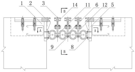
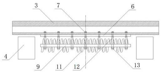
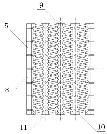
[0023] see Figure 1 to Figure 5 , a shock-absorbing expansion joint based on a wire rope damper of the present invention, comprising side longitudinal beams 2, middle longitudinal beams 3 and displacement boxes 4, the side longitudinal beams 2 are fixedly arranged on the beam end 1, and the inside of the beam end 1 is fixedly arranged with Displacement box 4, a load-bearing beam is installed between the two displacement boxes 4 facing the beam ends, and a plurality of middle longitudinal beams 3 are placed on the load-bearing beam. A supporting steel plate 5 is fixedly arranged on the upper side, and a fixed rope clamp 8 is installed on the side of the supporting steel plate 5. A connecting steel plate 6 is installed on the bottom of the middle longitudinal beam 3, and an intermediate rope clamp 9 is installed on the bottom surface o...


PUM


Abstract

A damping expansion joint based on a steel wire rope damper comprises side longitudinal beams (2), a middle longitudinal beam (3) and a displacement box (4), and is characterized in that a supporting steel plate (5) is fixedly arranged on the side face of a beam end (1) below the side longitudinal beams (2), a fixing rope clamp (8) is installed on the side face of the supporting steel plate (5), and a connecting steel plate (6) is installed at the bottom of the middle longitudinal beam (3); middle rope clamps (9) are installed on the bottom faces of the connecting steel plates (6) through connecting pieces, steel wire rope dampers are installed between the middle rope clamps (9) and the fixing rope clamps (8), and steel wire rope dampers (11) are also installed between every two adjacent middle rope clamps (9). The expansion joint has a multi-directional displacement function and can achieve a very good damping energy dissipation and shock absorption effect; the expansion joint can adapt to the earthquake, and also can reduce the impact response generated by the vehicle load; meanwhile, the conditions that the middle longitudinal beams are not uniformly displaced and the spacing is not uniform are avoided.

Description

technical field [0001] The invention relates to a shock-absorbing expansion joint, in particular to a shock-absorbing expansion joint based on a wire rope damper, and belongs to the technical field of roads and bridges. Background technique [0002] The bridge expansion device is an important connecting part between the beam ends of the bridge. Its performance directly affects the use of the bridge. In addition to meeting the telescopic function, the bridge expansion device also needs to withstand the repeated rolling and impact of the vehicle load. At the same time, it also needs to Control the vibration and driving noise of the vehicle within the allowable range, and maximize the driving comfort. [0003] The existing bridge telescopic devices are mainly modular telescopic devices and comb plate telescopic devices, in which the load-bearing sliding components (beams, middle beams and support frames) of the modular telescopic devices are all supported on elastic supports. ...

Claims


Application Information

Patent Timeline
Patent Type & Authority Applications(China)
IPC IPC(8): E01D19/06E01D19/08E01D101/30
CPCE01D19/06E01D19/062E01D19/083E01D2101/30
Inventor 万维东
Owner 武汉东九永环工程技术有限公司
Features
  • R&D
  • Intellectual Property
  • Life Sciences
  • Materials
  • Tech Scout
  • Unparalleled Data Quality
  • Higher Quality Content
  • 60% Fewer Hallucinations
Learn More