Large-swing-angle swing aligning device

A large swing angle and self-aligning technology, which is applied in the direction of shafts and bearings, mechanical equipment, pivots, etc., can solve problems such as difficult adjustment, excessive wear and tear, and inability to meet the needs of small products with large swing angles.

Pending Publication Date: 2021-09-10
ZHEJIANG JINGJIU BEARINGS
View PDF0 Cites 2 Cited by
  • Summary
  • Abstract
  • Description
  • Claims
  • Application Information

AI Technical Summary

Problems solved by technology

[0003] Due to the assembly method of the extruded outer ring, the hardness of the outer ring should not be too high, generally below HRC35, otherwise it will be difficult to extrude. During the use of the finished product, the outer spherical surface of the joint ball and the inner spherical surface of the outer ring are in hard friction If the hardness of the outer ring is low, the wear will be too fast and the service life will be shortened; for the extrusion assembly method, after the extrusion is completed, the rolling gap between the outer ring and the joint ball needs to be adjusted, otherwise it cannot swing. It is also very difficult to adjust the rolling clearance to be consistent with the entire contact surface. If the adjustment is not good, it will cause local stagnation or unsmooth swing; the swing angle is determined by the thickness of the joint ball and the thickness of the outer ring. If you want to increase the swing angle, you can reduce the thickness of the outer ring or increase the thickness of the joint ball, but reducing the thickness of the outer ring will reduce the radial load, and increasing the thickness of the joint ball will increase the product volume or There is a phenomenon that the end surface of the joint ball is too small and cannot be increased, it is difficult to realize the function of increasing the swing angle under the original size, and it cannot meet the use requirements of small products with a large swing angle

Method used


Image

  • Large-swing-angle swing aligning device
  • Large-swing-angle swing aligning device
  • Large-swing-angle swing aligning device

Examples


Embodiment Construction

[0023] The following will clearly and completely describe the technical solutions in the embodiments of the present invention with reference to the accompanying drawings in the embodiments of the present invention. Obviously, the described embodiments are only some, not all, embodiments of the present invention. Based on the embodiments of the present invention, all other embodiments obtained by persons of ordinary skill in the art without creative work, any modifications, equivalent replacements, improvements, etc., shall be included in the protection scope of the present invention Inside.

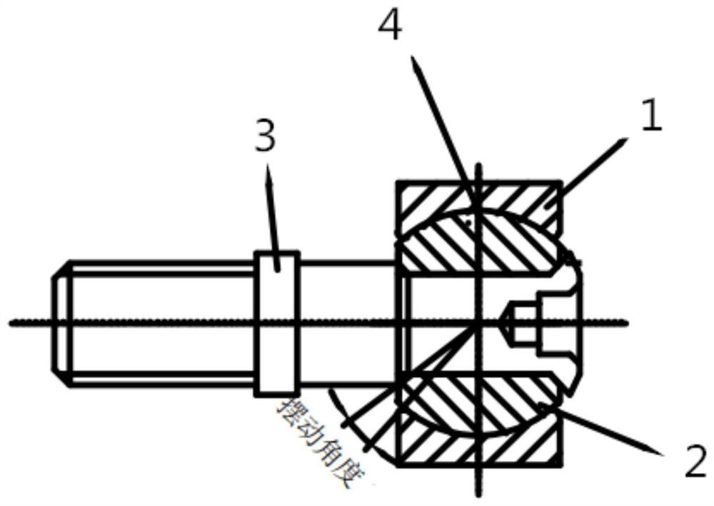
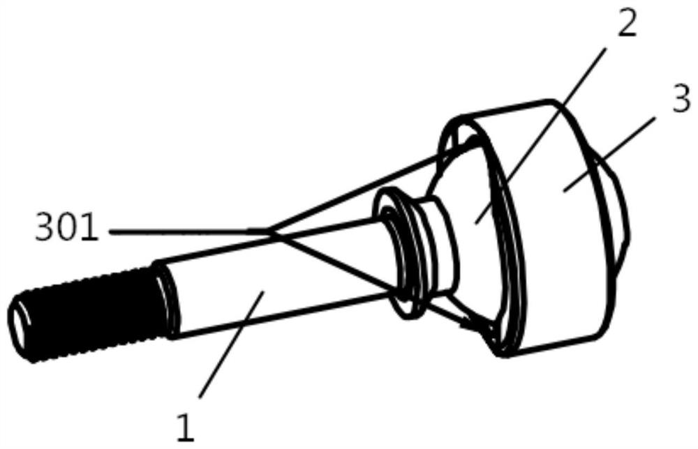
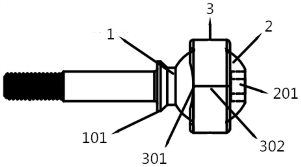
[0024] Such as Figure 2 to Figure 4 As shown, this embodiment discloses a large swing angle swing centering device, including a ball screw and an outer ring 3, the ball screw is sleeved in the outer ring 3 and the ball screw can rotate relative to the outer ring 3; The ball screw includes a ball head part 2 and a screw part 1. A protective flange 101 is integrally formed on the screw pa...


PUM


Abstract

The invention discloses a large-swing-angle swing aligning device which comprises a ball head screw and an outer ring, and the ball head screw is connected into the outer ring in a sleeved mode and can rotate relative to the outer ring. The ball head screw comprises a ball head piece and a screw piece, the ball head piece is connected with one end of the screw piece, the ball head piece is sleeved with the outer ring, and the outer side wall of the ball head piece makes contact with the inner side wall of the outer ring. The outer ring is in a circular tube shape, a mounting groove is formed in the inner side face of the outer ring, the mounting groove is in a spherical surface shape, the ball head piece is connected into the mounting groove in a sleeved mode, and a mounting gap is formed in the side wall of the outer ring and penetrates through the outer ring in the axis direction of the outer ring. When the ball head piece is inserted into the outer ring, the mounting gap is in an open state, and when the ball head piece enters the mounting groove, the mounting gap is in a closed state.

Description

technical field [0001] The invention relates to the field of machinery, in particular to a large swing angle swing centering device. Background technique [0002] The structure of existing self-aligning parts or ball stud bearings is as follows: figure 1 As shown, it consists of an outer ring 1, a joint ball 2, and a screw 3. The assembly method is to pass the screw 3 through the inner hole of the joint ball 2, and use riveting to form a whole ball screw, and then the ball screw Put the ball head part into the outer ring 1 and assemble it by extruding the outer ring. After the assembly is completed, adjust the rolling gap 4 between the joint ball 2 and the outer ring 1 to achieve the purpose of rotation or swing. [0003] Due to the assembly method of the extruded outer ring, the hardness of the outer ring should not be too high, generally below HRC35, otherwise it will be difficult to extrude. During the use of the finished product, the outer spherical surface of the joint...

Claims


Application Information

Patent Timeline
Patent Type & Authority Applications(China)
IPC IPC(8): F16C11/06
CPCF16C11/0614
Inventor 姚勇伟
Owner ZHEJIANG JINGJIU BEARINGS
Why Eureka
Try Eureka