Reflux bending pipe auxiliary device and ball screw using same

A technology of return elbow and ball screw, which is applied in transmission devices, belts/chains/gears, mechanical equipment, etc. It can solve problems such as poor connection smoothness of return channels, bending deformation of finished products, and difficult processing.

Active Publication Date: 2021-09-10
PRECISION MOTION INDS
View PDF6 Cites 0 Cited by
  • Summary
  • Abstract
  • Description
  • Claims
  • Application Information

AI Technical Summary

Problems solved by technology

[0004] The constituent elements of the return pipe mentioned in the previous paragraph usually include the pipe body and the two-legged seat. As far as the existing specific implementation forms of the pipe body and the two-legged seat are concerned, they can be roughly divided into two types: one-piece type and split type. Each shape has its own advantages and disadvantages. Take the one-piece shape as an example. Plastic materials are usually used for injection molding. Although the components are the most streamlined, the longer the tube size, the higher the probability of bending deformation of the finished product. Therefore, for The structural conditions of some ball screws are not suitable; taking the split structure as an example, usually the elbow section of the tube body is inserted into the foot seat at a vertical angle, and the extension direction of the tube body is set in the same direction as the screw The extension axes of the nuts are obliquely staggered with each other, so there are still some problems and disadvantages in its application, such as the exposed volume of the tube body is too large, the combination of the tube body and the foot seat is not stable, and the processing is not easy (For example, multi-axis processing is required) and the smoothness of the connection of the return channel is not good, etc.; and the present invention is an innovative breakthrough especially for this kind of split ball screw return structure

Method used


Image

  • Reflux bending pipe auxiliary device and ball screw using same
  • Reflux bending pipe auxiliary device and ball screw using same
  • Reflux bending pipe auxiliary device and ball screw using same

Examples


Embodiment Construction

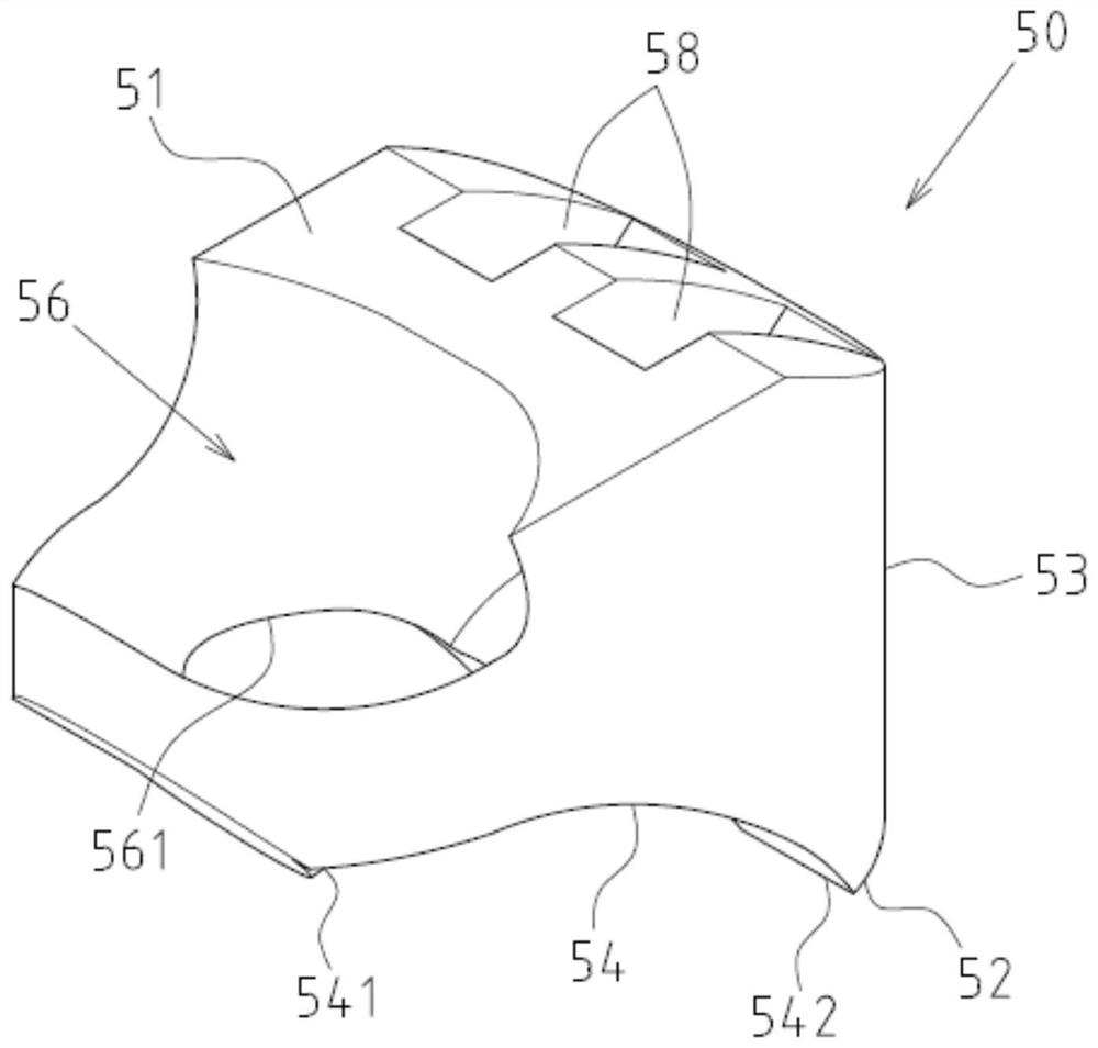
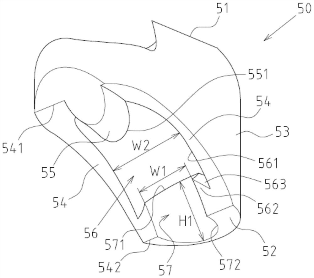
[0027] see Figure 1 to Figure 9 Shown are the preferred embodiments of the return elbow auxiliary device and the ball screw applying it according to the present invention, but these embodiments are for illustration only, and are not limited by this structure in the patent application.

[0028] The return elbow auxiliary device 50 is used to install a groove 24 for installation on the outside of the nut 20 of a ball screw 100, so as to be combined with a return elbow 40 to form a ball return channel; the return elbow The pipe auxiliary device 50 includes a top surface 51, a bottom end 52 and a peripheral wall 53. The peripheral wall 53 is in the shape of a vertical wall relative to a radial base line L2 defined by the nut 20, and an arc is formed on one side of the bottom end 52. Surface 54, the arc surface 54 includes a rising end 541 and a descending end 542, the descending end 542 is connected with the bottom end 52, and the arc surface 54 protrudes downwards adjacent to th...


PUM


Abstract

The invention discloses a reflux bending pipe auxiliary device and a ball screw using the same. The reflux bending pipe auxiliary device mainly comprises a top face, a bottom end and a peripheral wall, the peripheral wall is in a vertical wall face shape relative to a radial base line defined by a nut, an arc-shaped face is formed in one side of the bottom end, an inclined pipe inserting hole extending downwards is formed in the top face, the inclined pipe inserting hole extends downwards at an inclined angle relative to the radial base line, one part of the lower end of the inclined pipe inserting hole penetrates out to form a penetrating opening, a partition wall thickness is formed between the other part of the lower end of the inclined pipe inserting hole and the bottom end to form a stop end wall, and an embedding and clamping part is further formed in the stop end wall; a connecting surface is formed in the inner side of the partition wall thickness, and a inner diameter of the connecting surface is smaller than that of the inclined pipe inserting hole.

Description

technical field [0001] The invention relates to a ball screw; in particular, it refers to a structure of a return elbow auxiliary device of the ball screw. Background technique [0002] In terms of the structure design of the ball screw, the part related to the ball return flow has always been one of the key points for the development and breakthrough of related industries. [0003] According to the relevant previous technical data at present, the forms adopted by the ball reflux are mainly divided into two types: outer circulation type and inner circulation type, and the present invention especially discusses the structure form of the outer circulation type among them, and then discusses the outer circulation type As far as the structure is concerned, it mainly uses a return pipe to guide and displace several rollers (balls or rollers) from one part of the nut to another. [0004] The constituent elements of the return pipe mentioned in the previous paragraph usually inclu...

Claims


Application Information

Patent Timeline
Patent Type & Authority Applications(China)
IPC IPC(8): F16H25/22
CPCF16H25/2219F16H25/2228
Inventor 萧建富易崇皓
Owner PRECISION MOTION INDS
Why Eureka
Try Eureka