Capacitor parallel structure applied to power electronic device

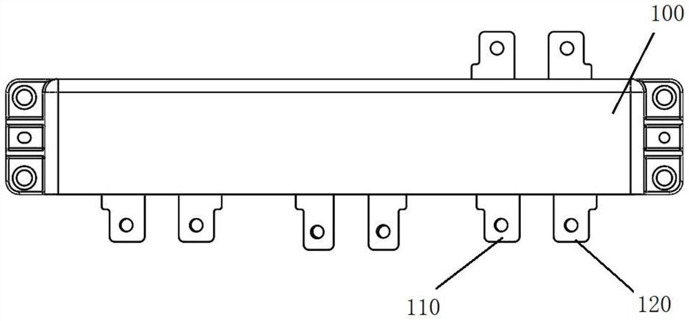
A technology of power electronic devices and capacitors, which is applied to multiple fixed capacitors, components of fixed capacitors, and terminals of fixed capacitors, etc., which can solve problems such as uneven heat, affecting the internal current distribution of capacitors, and affecting core heating.

Active Publication Date: 2021-09-10
SHANGHAI LINGANG POWER ELECTRONICS RES INST CO LTD
View PDF6 Cites 1 Cited by
  • Summary
  • Abstract
  • Description
  • Claims
  • Application Information

AI Technical Summary

Problems solved by technology

Taking film capacitors as an example, a multi-core parallel scheme is often used to achieve a large capacitance value. Due to structural asymmetry, the path impedance of each parallel core will be different, which will affect the current distribution inside the capacitor, and ultimately affect each capacitor. The heating of the core, there is a problem of heat unevenness and the risk of heat damage

Method used


Image

  • Capacitor parallel structure applied to power electronic device
  • Capacitor parallel structure applied to power electronic device

Examples


Embodiment Construction

[0029] The advantages of the present invention will be further elaborated below in conjunction with the accompanying drawings and specific embodiments.

[0030] Reference will now be made in detail to the exemplary embodiments, examples of which are illustrated in the accompanying drawings. When the following description refers to the accompanying drawings, the same numerals in different drawings refer to the same or similar elements unless otherwise indicated. The implementations described in the following exemplary examples do not represent all implementations consistent with the present disclosure. Rather, they are merely examples of apparatuses and methods consistent with aspects of the present disclosure as recited in the appended claims.

[0031] The terminology used in the present disclosure is for the purpose of describing particular embodiments only, and is not intended to limit the present disclosure. As used in this disclosure and the appended claims, the singular...


PUM


Abstract

The invention provides a capacitor parallel structure applied to a power electronic device, which comprises at least two capacitor cores arranged on a capacitor busbar, each capacitor core is connected between switch assemblies to form an output loop, the capacitor busbar is provided with a busbar terminal pair electrically connected with each capacitor core, an electric connecting wire is arranged between the capacitor core and the busbar terminal pair, so that one capacitor busbar and one busbar terminal pair are formed in pairs; and the capacitance value of the capacitor core farther from the busbar terminal pair is larger, so that the product of the capacitance value of each capacitor core and the capacitance total loop stray inductance is the same. After the technical scheme is adopted, heat dissipation of the capacitor core can be homogenized, and stray inductance can be balanced.

Description

technical field [0001] The invention relates to the field of motor control, in particular to a capacitor parallel structure applied to power electronic devices. Background technique [0002] In electronic devices, often due to high-frequency use, the capacitors in them generate a lot of heat. This part of heat will cause thermal damage to electronic devices due to long-term generation. [0003] Not only that, but in addition to generating heat, it will also generate uneven heat. Taking film capacitors as an example, a multi-core parallel scheme is often used to achieve a large capacitance value. Due to structural asymmetry, the path impedance of each parallel core will be different, which will affect the current distribution inside the capacitor, and ultimately affect each capacitor. The heating of the core has the problem of heat unevenness and the risk of heat damage. [0004] Therefore, there is a need for a new capacitor parallel structure, which can even out the heat...

Claims


Application Information

Patent Timeline
IPC IPC(8): H01G4/38H01G4/228
CPCH01G4/38H01G4/228
Inventor 夏雨昕李一粟
Owner SHANGHAI LINGANG POWER ELECTRONICS RES INST CO LTD
Why Eureka
Try Eureka