Hydrogen fuel cell stack structure

A fuel cell stack and electric stack technology, which is applied to fuel cells, circuits, electrical components, etc., can solve problems such as low efficiency, fatigue failure of bolts, and low strength of bolted joints.

Pending Publication Date: 2021-09-10
上海氢晨新能源科技有限公司
View PDF5 Cites 1 Cited by
  • Summary
  • Abstract
  • Description
  • Claims
  • Application Information

AI Technical Summary

Problems solved by technology

Therefore, the existing fixing methods easily lead to the following problems: 1) when the stack is assembled, bolts must be assembled, resulting in low assembly efficiency; 2) the strength of the bolt connection is low, which may cause fatigue damage to the bolts for a long time Reduced reliability

Method used


Image

  • Hydrogen fuel cell stack structure
  • Hydrogen fuel cell stack structure
  • Hydrogen fuel cell stack structure

Examples


Embodiment 1

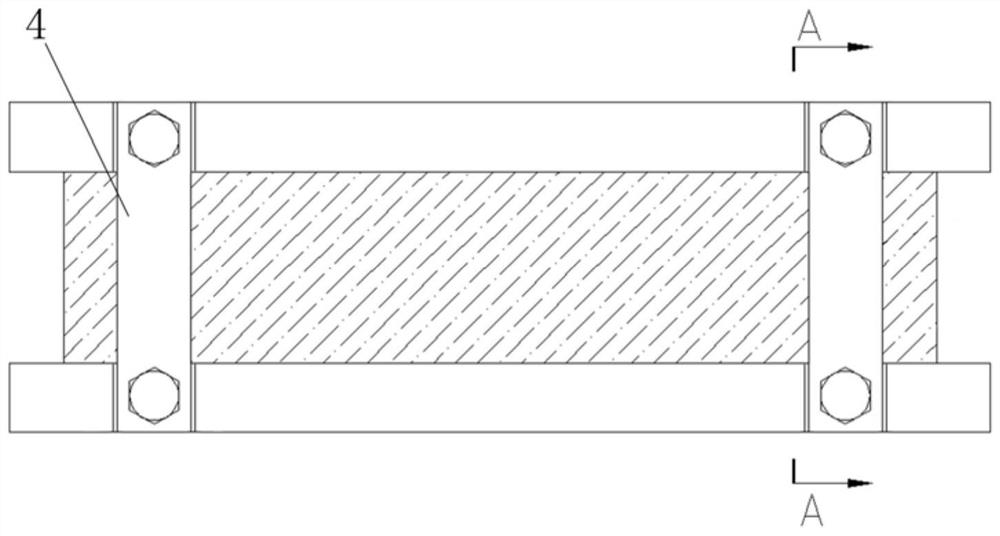
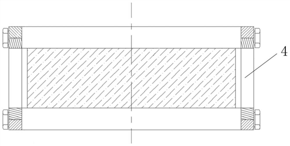
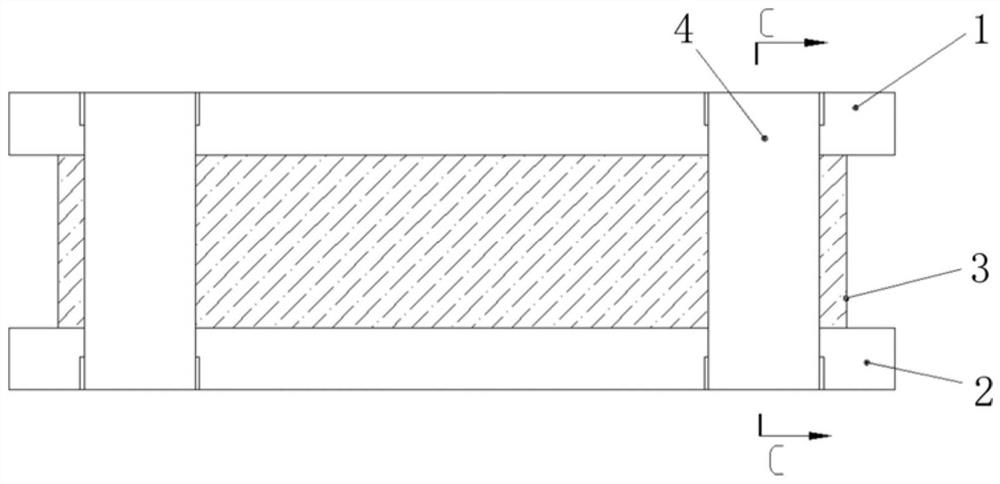
[0030] Such as Figure 3-5 As shown, this embodiment provides a hydrogen fuel cell stack structure, including an upper end plate 1 of the stack, a lower end plate 2 of the stack, a core 3 of the stack and a plurality of tie rods 4 . The electric stack core 3 is a conventional electric stack core 3 composed of bipolar plates and membrane electrodes. The stack core 3 is fixed between the upper end plate 1 of the stack and the lower end plate 2 of the stack, and the sides of the end plates are directly fixed by tie rods 4 . The number of pull rods 4 is at least four to ensure the strength of the installation. In this embodiment, four are preferred, and they are symmetrically arranged on both sides of the upper end plate 1 of the electric stack and the lower end plate 2 of the electric stack. The concrete structure of end plate and tie rod 4 is as follows:

[0031] Barbs 41 are provided at the top and bottom of each pull rod 4 . The barb 41 is a trapezoidal block, and the shor...

Embodiment 2

[0034] The overall structure of this embodiment is basically the same as that of Embodiment 1, the difference is that: Figure 6 As shown, the two ends of the tie rod 4 are "T"-shaped ends 43, the upper end plate 1 of the electric stack and the lower end plate 2 of the electric stack are provided with "T"-shaped fitting grooves, and the two ends of the tie rod 4 are respectively embedded and fitted. in the slot. The "T"-shaped fitting connection is conducive to improving the strength of installation and fixing, and has the functions of positioning and foolproofing.

Embodiment 3

[0036] The overall structure of this embodiment is basically the same as that of Embodiment 1, the difference is that: Figure 7 As shown, the barb 41 is provided with a positioning rib 42 , and the positioning rib 42 is vertically arranged at the center of the barb 41 . A longitudinal gap is provided in the slot 5 for embedding the positioning rib 42 . The positioning rib 42 can play the role of positioning support and improve the positioning progress of the end plate and the tie rod 4. It is only necessary to fix and fit the positioning rib 42, so that both sides of the tie rod 4 can have a certain redundant gap and reduce the difficulty of installation. .


PUM

PropertyMeasurementUnit
angleaaaaaaaaaa

Abstract

The invention relates to a hydrogen fuel cell stack structure, which comprises a stack upper end plate, a stack lower end plate, a stack core and a plurality of pull rods, the stack upper end plate and the stack lower end plate are respectively arranged on the upper surface and the lower surface of the stack core, the top end of each pull rod is connected with the stack upper end plate, the bottom end of each pull rod is connected with the stack lower end plate, the top end and the bottom end of each pull rod are provided with barbs, clamping grooves corresponding to each other in position are formed in the stack upper end plate and the stack lower end plate; and the barbs of the pull rods are clamped into the clamping grooves to clamp the stack upper end plate and the stack lower end plate. Compared with the prior art, the end plate is directly fixed through the pull rod, bolt fixing in a traditional structure is not needed, the installation efficiency is high, and operation is convenient.

Description

technical field [0001] The invention relates to the field of hydrogen fuel cells, in particular to a hydrogen fuel cell stack structure. Background technique [0002] A fuel cell is a power generation device that generates electricity through electrochemical reactions of hydrogen and oxygen. It has many advantages such as high energy conversion efficiency, environmental friendliness, and low noise. With the development and commercialization of fuel cell technology, the safety and durability of fuel cells have received more and more attention. Hydrogen fuel cell stacks usually use tie rods for fixed installation of end plates. Its conventional structure is as figure 1 and figure 2 As shown, the tie rod is installed on one side of the lower and upper end plates, and the two ends are fixed by bolts and end plates. As a result, the existing fixing methods easily lead to the following problems: 1) when the stack is assembled, bolts must be assembled, resulting in low assembl...

Claims


Application Information

Patent Timeline
Patent Type & Authority Applications(China)
IPC IPC(8): H01M8/247H01M8/22
CPCH01M8/247H01M8/22Y02E60/50
Inventor 徐一凡程旌德
Owner 上海氢晨新能源科技有限公司
Why Eureka
Try Eureka