
Manufacturing method of battery roll core and battery roll core

A manufacturing method and technology of battery rolls, which can be applied to battery electrodes, non-aqueous electrolyte battery electrodes, secondary batteries, etc., and can solve problems such as loose bonding, abnormality, and uneven lithium insertion in the negative electrode sheet

Active Publication Date: 2021-09-10
APOWER ELECTRONICS CO LTD
View PDF8 Cites 1 Cited by
  • Summary
  • Abstract
  • Description
  • Claims
  • Application Information

AI Technical Summary

Problems solved by technology

[0004] 1. The battery core obtained by the conventional winding method, the structure of the core is affected by factors such as the material of the diaphragm, the longitudinal shrinkage of the diaphragm, the thickness of the positive and negative electrodes, and the expansion of the electrode during charging. It is easy to have loose fit with the diaphragm;
[0005] 2. The battery core obtained by the conventional winding method is affected by external factors such as the parameters of the winding process and the high-temperature fixture in the production process, which exerts pressure on the thickness direction of the battery core. Inadequate bonding occurs. Once the pole pieces in the arc-shaped edge area of ​​the winding core structure are not tightly bonded, it will cause uneven lithium insertion in the negative electrode sheet in this area, resulting in black spots and abnormal lithium precipitation, which will directly affect the battery core. capacity, cycle life and safety

Method used


Image

  • Manufacturing method of battery roll core and battery roll core
  • Manufacturing method of battery roll core and battery roll core
  • Manufacturing method of battery roll core and battery roll core

Examples


Embodiment Construction

[0029] In order to make the technical problems solved by the present invention, the technical solutions adopted and the technical effects achieved clearer, the technical solutions of the embodiments of the present invention will be further described in detail below in conjunction with the accompanying drawings. Obviously, the described embodiments are only the technical solutions of the present invention. Some, but not all, embodiments. Based on the embodiments of the present invention, all other embodiments obtained by those skilled in the art without creative efforts fall within the protection scope of the present invention.

[0030] In the description of the present invention, unless otherwise clearly specified and limited, the terms "connected", "connected" and "fixed" should be understood in a broad sense, for example, it can be a fixed connection, a detachable connection, or an integrated ; It can be a mechanical connection or an electrical connection; it can be a direct...


PUM


Abstract

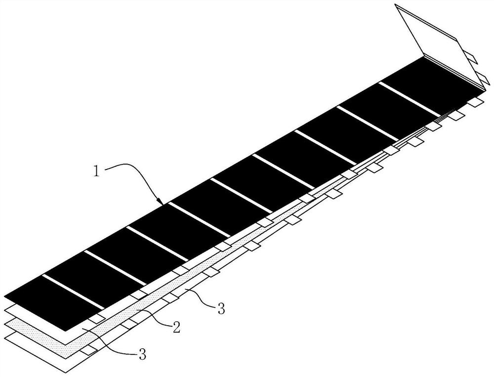
The invention discloses a manufacturing method of a battery roll core and a battery roll core. The manufacturing method of the battery roll core comprises the following steps that: step S10, a negative electrode current collector, a positive electrode current collector and at least two diaphragms are provided, the negative electrode current collector is coated with negative electrode slurry, the negative electrode slurry forms at least two convex parts on at least one side surface of the negative electrode current collector, and two adjacent convex parts are distributed at intervals along the extension direction of the negative electrode current collector, so that a negative electrode plate can be obtained, the positive electrode current collector is coated with positive electrode slurry, so that a positive electrode plate can be obtained; and step S20, the positive electrode plate, the diaphragm, the negative electrode plate and the diaphragm are overlapped, the first end of the positive electrode plate is wound, so that a flat roll core can be formed, and the convex parts cover the arc-shaped structure surface of the roll core on the negative electrode plate. According to the manufacturing method of the battery roll core and the battery roll core, more lithium embedding space can be provided for the negative electrode plate, so that the risk of lithium precipitation of the battery roll core is reduced.

Description

technical field [0001] The invention relates to the technical field of batteries, in particular to a method for manufacturing a battery winding core and the battery winding core. Background technique [0002] Polymer lithium-ion batteries have many advantages such as high energy density, miniaturization, ultra-thinness, light weight, high safety and low cost, and are used in smart phones and portable devices. [0003] Generally, the polymer battery core adopts the conventional winding method of double-sided single-layer coating, that is, the active material of the positive and negative electrodes is evenly coated on the substrate, and then the conventional winding method is used to make the roll. Core structure, and then packaged with aluminum-plastic film to obtain a battery core. The battery winding core obtained by this kind of manufacturing method has the following disadvantages: [0004] 1. The battery core obtained by the conventional winding method, the structure of...

Claims


Application Information

Patent Timeline
IPC IPC(8): H01M10/0587H01M4/13H01M4/139H01M10/0525H01M10/42
CPCH01M10/0587H01M4/13H01M4/139H01M10/0525H01M10/4235Y02P70/50Y02E60/10
Inventor 闵幸福陈俊涛郭建伟
Owner APOWER ELECTRONICS CO LTD
Learn More