
Method for monitoring the operating state of a hydromechanical unit

A hydraulic machinery and state technology, applied in mechanical equipment, engine components, engine functions, etc., can solve problems such as engine surge or flameout, high operating costs, etc.

Pending Publication Date: 2021-09-10
SAFRAN AIRCRAFT ENGINES SAS
View PDF3 Cites 0 Cited by
  • Summary
  • Abstract
  • Description
  • Claims
  • Application Information

AI Technical Summary

Problems solved by technology

Therefore, any degradation at the FMU level will affect these regularities and may lead to a risk of engine surge or stall
[0028] In addition to the cost of repairing or replacing equipment, the operating costs associated with engine failure can be significant for an aircraft in operation

Method used

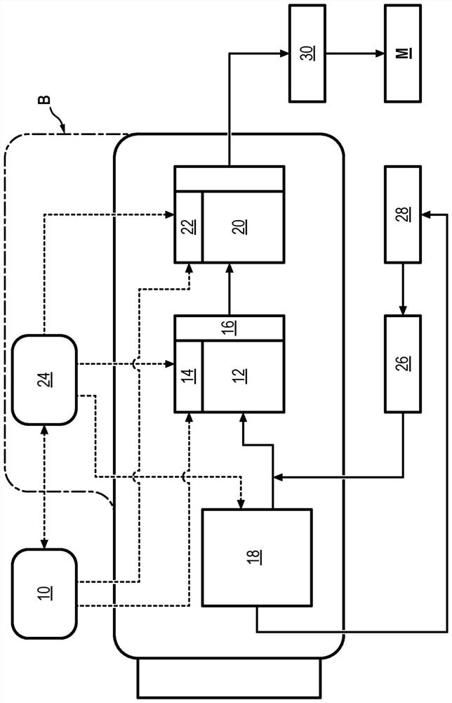

Image

  • Method for monitoring the operating state of a hydromechanical unit
  • Method for monitoring the operating state of a hydromechanical unit
  • Method for monitoring the operating state of a hydromechanical unit

Examples


no. 1 example

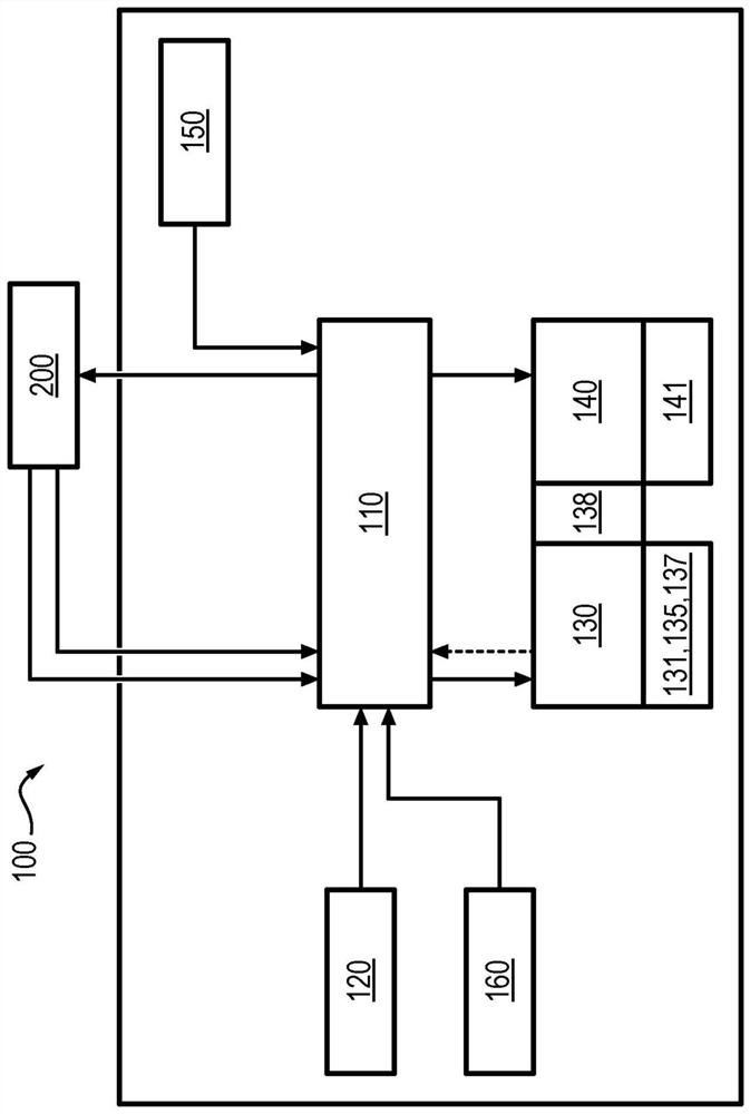
[0103] The monitoring module 300 can be used as figure 1 or figure 2 implemented in the control unit of the control device.

[0104] Optionally, the monitoring module 300 can be figure 2 The electronic card 110 of the control device is implemented.

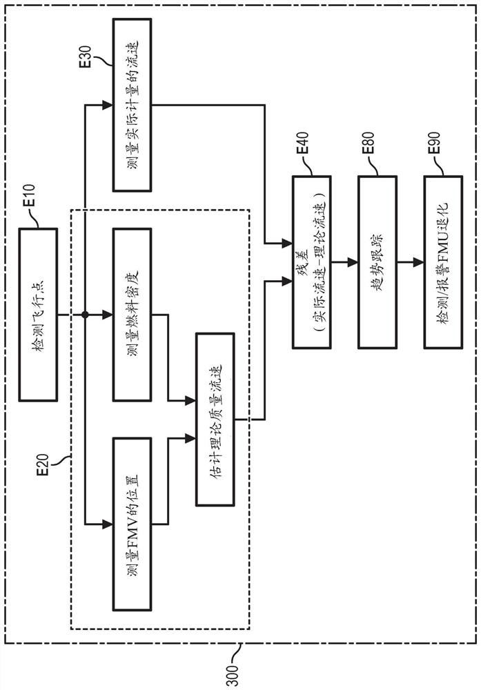
[0105] The monitoring module 300 is configured to use the measurement of the mass flow rate to detect a drift in the metrology law of the hydromechanical unit compared to the initial calibration by analyzing several predefined points in the flight envelope: this is the hydromechanical unit aging or internal signs of degradation.

[0106] In the following description, reference is made to figure 2 A control device to describe the method according to the first embodiment. Of course, this method can be applied to figure 1controls shown.

[0107] The accuracy of the measurement or estimation of mass flow rate depends on the metered flow rate. Therefore, the method is used for different stabilization points of the flight env...

no. 2 example

[0131] Such as figure 2 As mentioned above, the monitoring module 300 can be implemented in the control unit or the electronic card 110 of the control device.

[0132] refer to Figure 4 , in step E10, as in the first embodiment, the step of determining the detection of the flying point is performed.

[0133] In step E20', the temperature sensor 160 acquires the temperature. Simultaneously or alternatively, the position sensor 131 acquires the position of the movable part 138 of the metering valve 130 . Simultaneously or alternatively, the differential pressure sensor 141 acquires the differential pressure at the ends of the metering valve 130 . Concurrently or alternatively, flow meter 150 acquires the flow rate.

[0134] The flow meter 150 can also be used indirectly as a density meter, which allows identification of the density of the fuel actually metered (depending on the type of fuel used and its temperature).

[0135] Alternatively, a density sensor other than a f...


PUM


Abstract

The present invention relates to a method for monitoring the operating state of a hydromechanical unit (100) of an aircraft turbomachine, comprising: a metering valve (130) comprising a mobile metering part (138), a regulating valve (140) configured to control the flow rate (Q) through the metering valve (130), a flow meter (150) able to measure the mass flow rate (Q) of fuel passing through, characterized in that a monitoring module (300) is configured to implement the following steps: (E20') determine a reconstructed flow rate on the basis of the position of the mobile part (138), and determine a measurement of the density of the fuel, - (E30) calculate a remnant, and compare said remnant to a determined threshold value, (E90) determine a state of abnormal operation of the hydromechanical unit dependent on the result of the comparison.

Description

technical field [0001] The invention relates to the field of fuel metering units or hydromechanical units on aircraft engines, in particular turbomachinery. [0002] The invention relates in particular to a method for monitoring the operating state of a turbomechanical hydromechanical unit of an aircraft. Background technique [0003] Current engines are equipped with a fuel metering unit, a hydromechanical unit commonly called an FMU. [0004] The hydromechanical unit has a variety of functions. It provides fuel metering, ie flow rate information with the required relative accuracy, which is generated by the aircraft's control unit according to the requirements specified during the flight phase. It also allows to cut off the fuel generated by the driver's command and to cut off and / or regulate the fuel flow rate in the emergency situation of overspeed detected by the speed sensors of the high and / or low pressure parts of the engine. Finally, it maintains the lowest press...

Claims


Application Information

Patent Timeline
Patent Type & Authority Applications(China)
IPC IPC(8): F02C7/232F02C9/26
CPCF02C9/263F02C7/232F05D2260/80
Inventor 阿诺德·伯纳德·克莱芒·托马斯·茹达雷夫吉列尔莫·阿尔西德·奥古斯特·弗莱特
Owner SAFRAN AIRCRAFT ENGINES SAS
Learn More