Busbar repairing method of storage battery with direct connection structure

A repair method and battery technology, applied in the direction of structural parts, battery pack parts, circuits, etc., can solve the problems of fusing, virtual welding, and poor adhesion of the plates

Active Publication Date: 2021-09-14
ZHEJIANG TIANNENG BATTERY JIANGSU +3
View PDF8 Cites 1 Cited by
  • Summary
  • Abstract
  • Description
  • Claims
  • Application Information

AI Technical Summary

Problems solved by technology

The direct connection of the busbar adopts the dipping structure, and the plate is continuously cast, and the lug is thin, and the quality problems that often occur are: code A-the slag inclusion of the pole lug causes false welding; code B-the side of the negative plate lug must be folded inward Bend, otherwise it will produce capillary phenomenon, and the plate will absorb glue to cause defects; code name C side negative ear is offset and false welding; code name D - ear ear is blown
[0003] The original method of repairing the quality problems of the above-mentioned busbars is to raise the busbars to pull out the tabs for direct welding, melt the tab material and then weld and repair, but now because the direct connection of the busbars adopts a dipped structure, At the same time, the plate adopts continuous casting, and the tab is relatively thin. If the above method is still used, it will easily cause secondary damage to the tab during the process of raising the busbar and leaking the tab. In order to solve this problem, it is necessary to find a more The best way to overcome the above problems

Method used


Image

  • Busbar repairing method of storage battery with direct connection structure
  • Busbar repairing method of storage battery with direct connection structure
  • Busbar repairing method of storage battery with direct connection structure

Examples


Embodiment Construction

[0021] The present invention will be described in detail below in conjunction with the accompanying drawings.

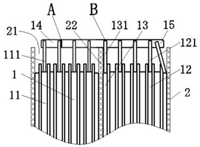
[0022] This implementation mode provides a method for repairing busbars of batteries with a direct connection structure, such as figure 1 As shown, the direct connection structure storage battery includes a pole group 1 and a battery tank 2. The pole group 1 is formed by connecting a number of positive bus bars 14 and negative bus bars 15 in series. The pole group 1 is provided with a positive plate 11, a negative plate 12 and a side Negative plate 13, the positive plate 11 is provided with a positive pole ear 111, the negative plate 12 is provided with a negative pole ear 121, and the side negative plate 13 is provided with a side negative pole ear 131; the positive pole ear 111, the negative pole ear 121 and the side negative pole ear 131 Respectively welded to the positive bus bar 14 and the negative bus bar 15; the battery slot 2 is provided with a number of sing...


PUM


Abstract

The invention relates to the field of storage batteries, and discloses a busbar repairing method of a storage battery with a direct connection structure. The busbar repairing method comprises the following steps of identifying and picking out poor pseudo soldering caused by slag inclusion of a tab, and cutting a slope notch at the slag inclusion; identifying and picking out poor glue adsorption of a polar plate caused by capillarity due to the fact that a side negative tab is not bent towards the inner side, correspondingly cutting off a section on each of the two sides of the side negative tab, then bending the side negative tab towards the inner side, and correspondingly cutting off slope notches on the sections on the two sides; identifying and picking out poor deviation pseudo soldering of the side negative tab, and cutting the slope notch at the virtual connection part of the side negative tab and a busbar; identifying and picking out poor fusing of the tab, and cutting a trumpet-shaped notch on the busbar right above the fusing part of the tab; and soldering tin wires are welded into the slope notches and the trumpet-shaped notches through an electric soldering iron correspondingly. According to the busbar repairing method, under the condition that the busbar is not lifted and the tab is pulled out, various defects of the busbar can be directly repaired and welded, so that the tab with relatively thin thickness can be prevented from secondary damage caused by repairing.

Description

technical field [0001] The invention relates to the field of storage batteries, in particular to a method for repairing busbars of storage batteries with a direct connection structure. Background technique [0002] The cast-welded structure of the electric vehicle battery basically adopts the busbar bridge-free connection structure, which has the problem of bridge breakage, and the bridge connection needs to consume more lead. At present, the improved design of the bridge-free structure of the battery into a bus-bar direct connection structure can greatly reduce the lead consumption of casting and welding, and the battery basically does not have the problem of broken cells, which improves the quality of the product. The direct connection of the busbar adopts the dipping structure, and the plate is continuously cast, and the lug is thin, and the quality problems that often occur are: code A-the slag inclusion of the pole lug causes false welding; code B-the side of the negati...

Claims


Application Information

Patent Timeline
Patent Type & Authority Applications(China)
IPC IPC(8): B23P6/00H01M50/502
CPCB23P6/00H01M50/502Y02E60/10
Inventor 李明钧李军魏妮妮胡国柱
Owner ZHEJIANG TIANNENG BATTERY JIANGSU
Why Eureka
Try Eureka