Secondary ejection structure for mould

A secondary ejection and mold technology, applied in the field of injection molds, can solve the problems of reducing product processing efficiency, time-consuming, increasing the ejection stroke of the ejection mechanism, etc.

Inactive Publication Date: 2021-09-14
鲲彤智能科技(芜湖)有限公司
View PDF10 Cites 2 Cited by
  • Summary
  • Abstract
  • Description
  • Claims
  • Application Information

AI Technical Summary

Problems solved by technology

[0003] However, after the plastic workpiece is ejected from the mold, it is easy to get stuck on the mold, and the workpiece cannot fall off automatically. Generally, when taking out the product from the mold, no matter whether a single or multi-component ejection mechanism is used, the ejection action is completed at one time. , but for products with special shapes, if the workpiece cannot be completely separated from the mold after one ejection or the workpiece cannot be separated by the ejection mechanism, manual demoulding is required, or the ejection stroke of the ejection mechanism needs to be increased. Time-consuming, reducing the efficiency of product processing

Method used


Image

  • Secondary ejection structure for mould
  • Secondary ejection structure for mould
  • Secondary ejection structure for mould

Examples


Embodiment 1

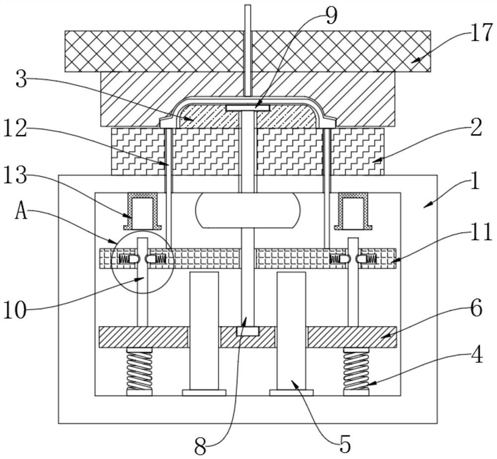
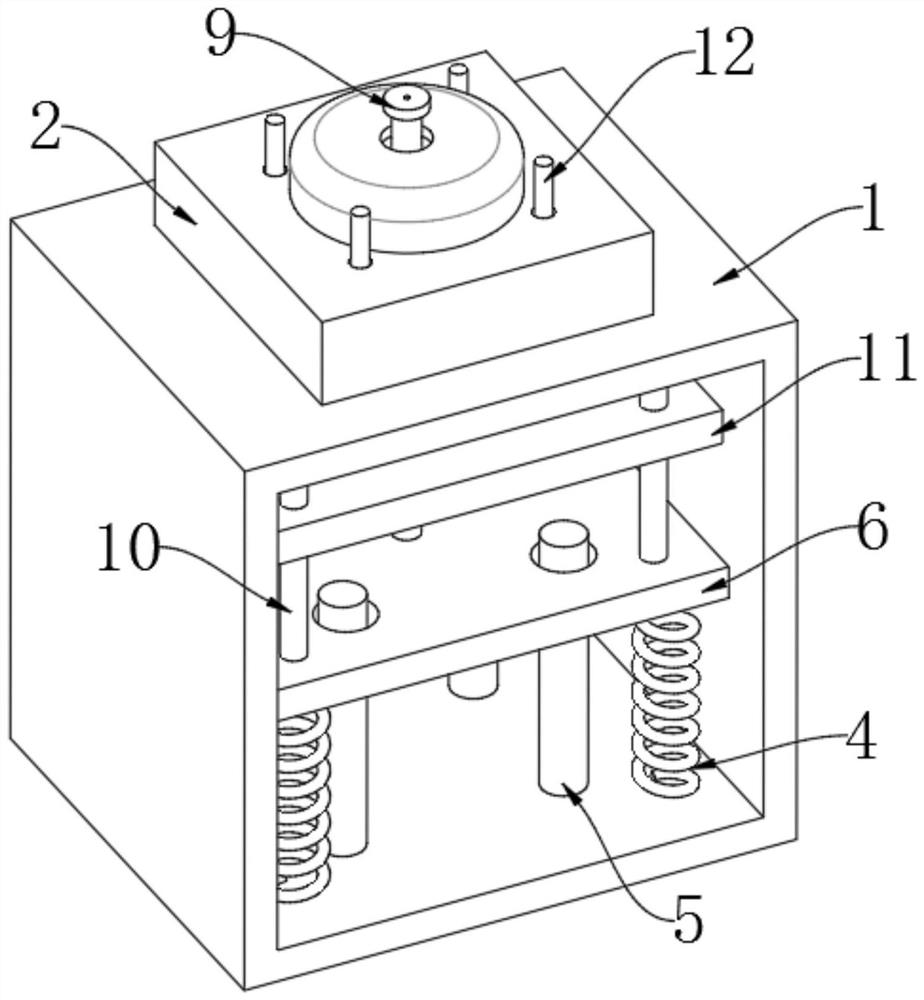
[0024] refer to Figure 1-4 , a secondary ejection structure for molds, including a movable mold assembly 17 and a fixed mold frame 1, the upper surface of the fixed mold frame 1 is fixed with a fixed mold installation block 2 by bolts, and the upper surface of the fixed mold installation block 2 The surface is fixedly connected with a fixed mold core 3 , and the inner bottom wall of the fixed mold frame 1 is respectively fixedly connected with four compression springs 4 and sliding guide columns 5 .

[0025] The surface of the sliding guide column 5 is slidably connected with a first push plate 6, the lower surface of the first push plate 6 is fixedly connected with the top of the compression spring 4, and the center of the upper surface of the first push plate 6 is fixedly equipped with a first push rod 8 , the top end of the first ejector rod 8 is fixedly connected with a demoulding push block 9 .

[0026] The upper surface of the first push plate 6 is fixedly connected wi...

Embodiment 2

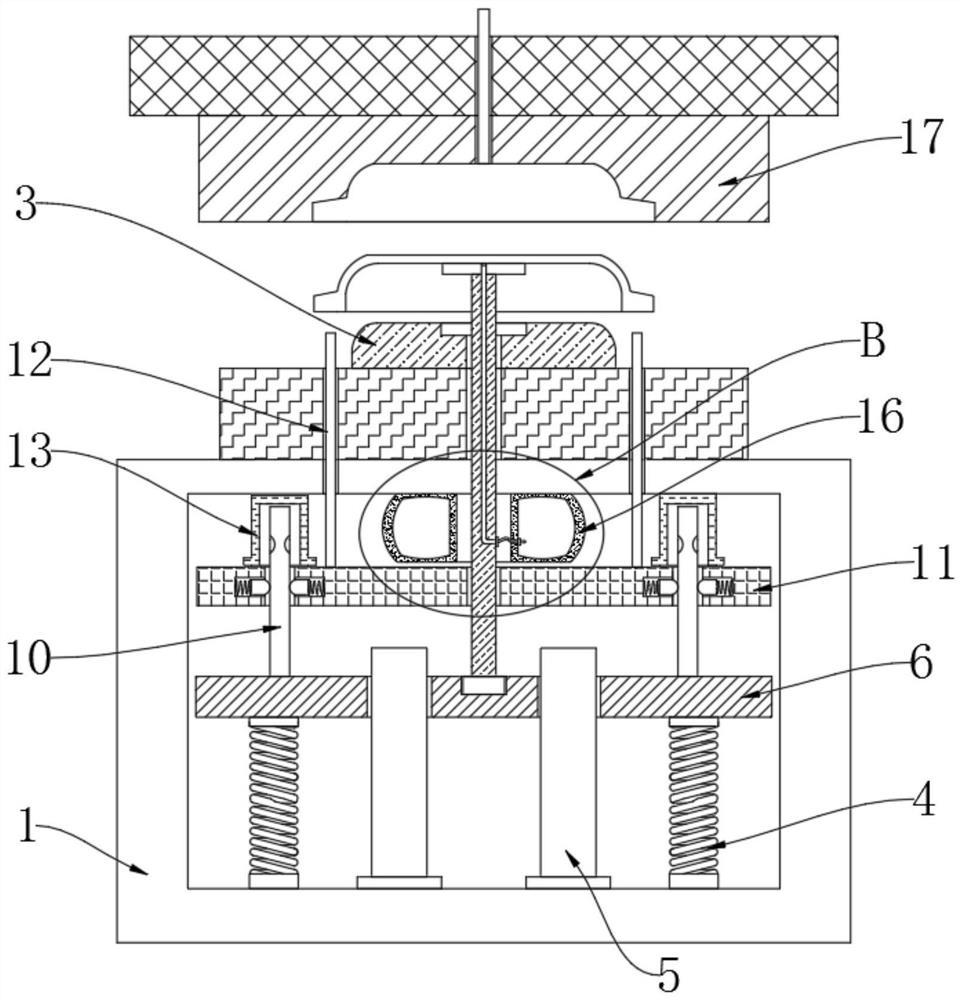
[0031] refer to Figure 5 , different from Embodiment 1, the inner top wall of the fixed frame is fixedly connected with a ring-shaped compressed air bag 16, and the upper surface of the demoulding push block 9 is provided with a demoulding air hole, and the opening of the demoulding air hole is provided with a one-way On the valve cover, the bottom end of the demoulding air hole extends to the surface of the first ejector pin 8 , the output port of the compressed air bag 16 communicates with the demoulding air hole through a flexible hose, and the first ejector pin 8 runs through the annular hole of the compressed air bag 16 .

[0032] In this embodiment, by setting the compressed air bag 16, the compressed air bag 16 is squeezed simultaneously during the ascent of the second push plate 11, and the gas is delivered to the demoulding air hole on the surface of the demoulding push block 9 through the compressed air bag 16, and then the air is released by the gas. The workpiece ...


PUM


Abstract

The invention discloses a secondary ejection structure for a mould, which comprises a movable mould assembly and a fixed mould frame; a fixed mould mounting block is fixedly mounted on the upper surface of the fixed mould frame through bolts; a fixed mould core is fixedly connected to the upper surface of the fixed mould mounting block; and the inner bottom wall of the fixed mould frame is fixedly connected with four compression springs and sliding guide columns respectively. According to the secondary ejection structure for the mould provided by the invention, through the arrangement of a first push plate, a first ejector rod, a second push plate and a second ejector rod, after injection moulding is completed, when the movable mould assembly ascends and is separated from the fixed mould core, the first push plate and the second push plate are driven to move upwards under the resilience force action of the compression spring; meanwhile, the first ejector rod and the second ejector rod are driven to complete two times of ejection operation in sequence, so that the effect of secondary mould ejection is achieved; the situation that a workpiece cannot be completely ejected out of a mould core due to traditional single mould ejection is avoided; manual assistance is not needed; automatic remoulding is achieved; and the machining efficiency is improved.

Description

technical field [0001] The invention relates to the technical field of injection molds, in particular to a secondary ejection structure for molds. Background technique [0002] At present, injection molds are used to produce similar circular plastic parts. The bottom surface or outer wall of this type of product is made with a convex ring or edge. When molding this type of product, traditional injection molds use the combination of direct ejector top and stripper plate. ejected. [0003] However, after the plastic workpiece is ejected from the mold, it is easy to get stuck on the mold, and the workpiece cannot fall off automatically. Generally, when taking out the product from the mold, no matter whether a single or multi-component ejection mechanism is used, the ejection action is completed at one time. , but for products with special shapes, if the workpiece cannot be completely separated from the mold after one ejection or the workpiece cannot be separated by the ejectio...

Claims


Application Information

Patent Timeline
Patent Type & Authority Applications(China)
IPC IPC(8): B29C45/40
CPCB29C45/401
Inventor 刘国春戴辉林徐荣华李诗华任海军王文军
Owner 鲲彤智能科技(芜湖)有限公司
Why Eureka
Try Eureka