Material receiving device of polaroid production equipment

A technology for production equipment and material receiving devices, which is used in transportation and packaging, mechanical conveyors, conveyor objects, etc., and can solve the problems of low degree of automation and low production efficiency.

Active Publication Date: 2021-09-14
深圳市运宝莱光电科技有限公司
View PDF12 Cites 0 Cited by
  • Summary
  • Abstract
  • Description
  • Claims
  • Application Information

AI Technical Summary

Problems solved by technology

[0003] Most of the receiving devices of the existing polarizer production equipment only have a simple stacking function. When the receiving device stacks more than 300 polarizers, manual intervention is required for transfer, and the low degree of automation leads to low production efficiency.

Method used


Image

  • Material receiving device of polaroid production equipment
  • Material receiving device of polaroid production equipment
  • Material receiving device of polaroid production equipment

Examples


Embodiment 1

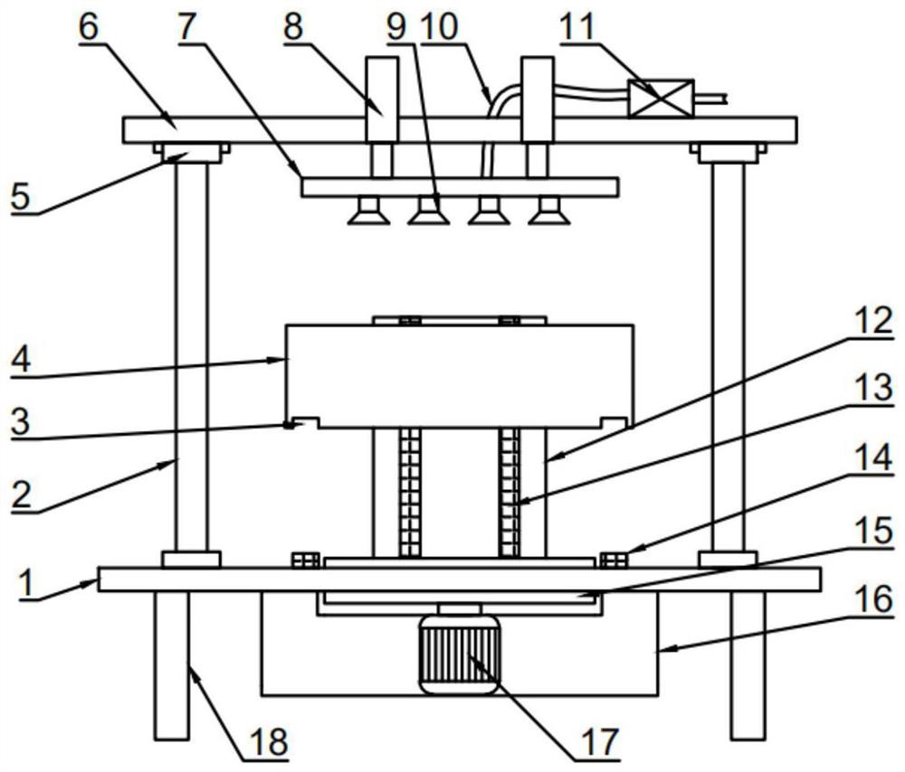
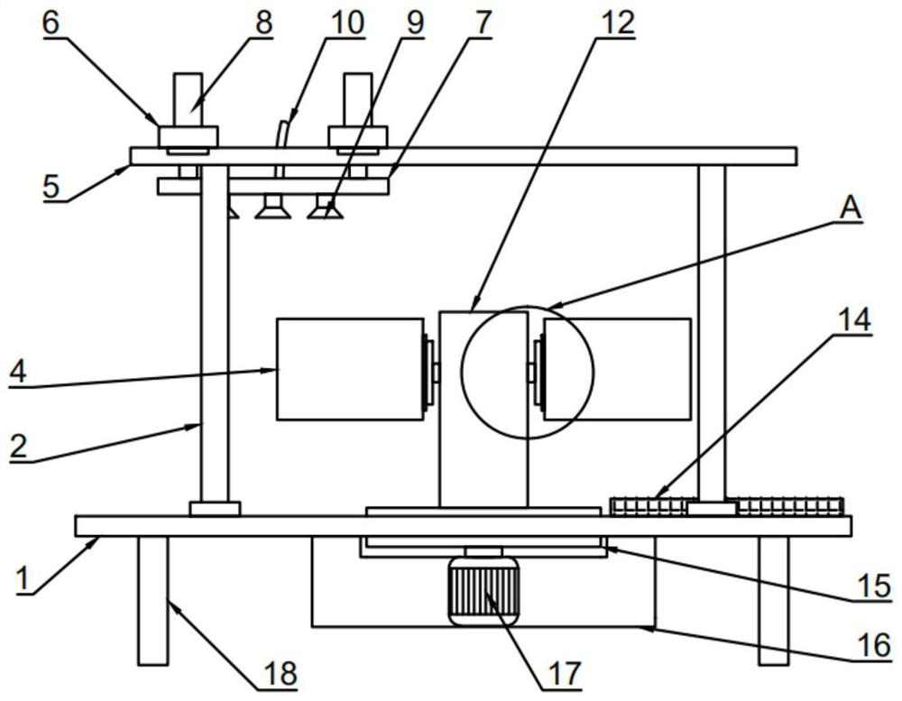
[0025] see figure 1 , 2 And 4, in the embodiment of the present invention, a material receiving device of polarizer production equipment includes a workbench 1, a support platform 16 is mounted and fixed on the workbench 1, and a turntable 15 is rotatably installed on the support platform 16, And the stepper motor 17 that is used to drive the rotation of the turntable 15 is also arranged in the supporting platform 16, the described supporting platform 16 is arranged through the workbench 1, and the described supporting platform 16 is also provided with a material receiving assembly, and the described material receiving assembly includes The support platform 12 and the receiving box 4, the support platform 12 is installed and fixed on the turntable 15, and two groups of second electric guide rails 13 are also symmetrically arranged on both sides of the support platform 12, and the material receiving box 4 passes through the magnetic attraction assembly Slidingly installed on t...

Embodiment 2

[0028] see Figure 1-6 , the difference between this embodiment and embodiment 1 is:

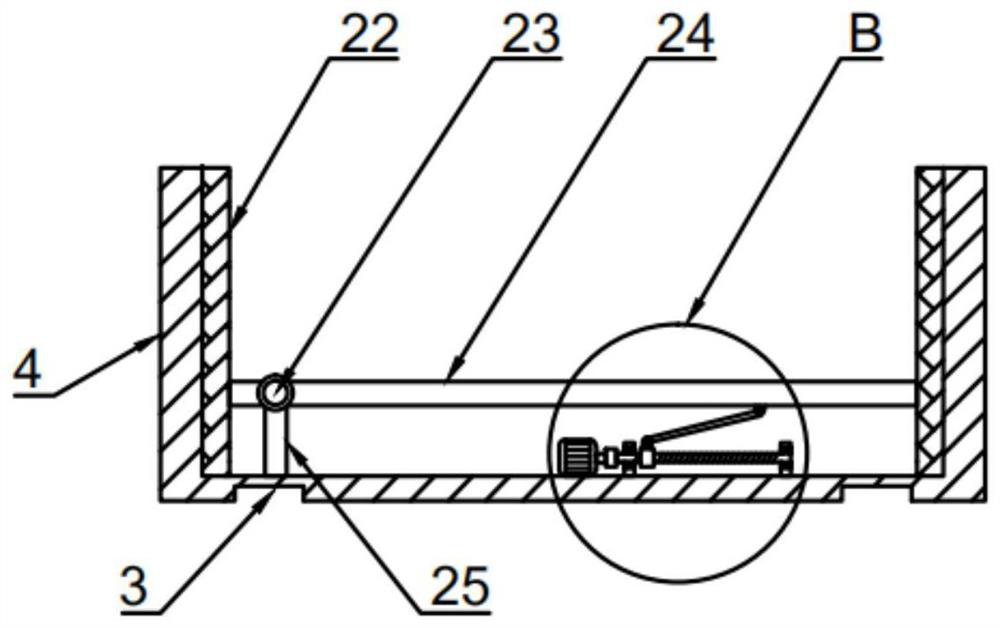
[0029]In this embodiment, the receiving box 4 is also provided with a support plate assembly for conveniently taking out the polarizer. The support plate assembly includes a support block 25 and a carrying plate 24, and the support block 25 is installed and fixed on the receiving plate. In the material box 4, one end of the loading plate 24 is installed on the support block 25 through the connecting shaft 23, and a screw assembly for driving the loading plate 24 to rotate on the support block 25 is also provided in the material receiving box 4. One end of the carrying plate 24 is rotated on the support block 25 with the connecting shaft 23 as the axis to make the other end of the carrying plate 24 tilt up. At this time, one end of the polarizer loaded in the receiving box 4 can be lifted from the receiving box 4 out, which is convenient for the staff to carry and use.

[0030] Described sc...


PUM


Abstract

The invention discloses a material receiving device of polaroid production equipment. The device comprises a workbench. A supporting table is installed and fixed on the workbench, a rotary table is rotationally installed on the supporting table, and a material receiving assembly is further arranged on the supporting table and comprises a supporting platform and a material receiving box. Two conveying guide rails used for conveying the material receiving box are further arranged on the workbench, and sliding grooves which are used in cooperation with the conveying guide rails are further formed in the material receiving box. Four supporting rods are further installed and fixed on the workbench, and first electric guide rails are further installed on the two supporting rods which are parallel to the conveying guide rails. A fixing plate is installed on the first electric guide rails in a sliding mode, a plurality of hydraulic cylinders are arranged on the fixing plate, a material receiving plate is installed and fixed at the ejection ends of the hydraulic cylinders, and a suction disc assembly used for absorbing and carrying polaroids is arranged on the material receiving plate. The device is novel in structure and practical in function, and the production efficiency of the polaroids is effectively improved.

Description

technical field [0001] The invention relates to the technical field of polarizer production, in particular to a material receiving device of polarizer production equipment. Background technique [0002] The full name of polarizer is polarizer. The imaging of liquid crystal display must rely on polarized light. All liquid crystals have two front and rear polarizers attached to the liquid crystal glass to form a liquid crystal sheet with a total thickness of about 1mm. If any one is missing Polarizers and LCDs cannot display images. Polarizers should be stored at room temperature with a humidity below 75% and protected from light; when stored, they must be placed flat, and every 300 sheets must be stacked on separate supports when stacked, and excessive stacking may easily cause damage to the polarizers. [0003] Most of the receiving devices of existing polarizer production equipment only have a simple stacking function. When the receiving device stacks more than 300 polariz...

Claims


Application Information

Patent Timeline
Patent Type & Authority Applications(China)
IPC IPC(8): B65G47/90B65G35/00
CPCB65G47/90B65G35/00
Inventor 陈运万富斌
Owner 深圳市运宝莱光电科技有限公司
Why Eureka
Try Eureka