A splicing device for polarizer production equipment

A technology for production equipment and material receiving devices, which is applied in the directions of transportation and packaging, mechanical conveyors, conveyor objects, etc., can solve the problems of low degree of automation and low production efficiency, and achieve the goal of reducing workload, convenient transportation, and convenient handling. Effect

Active Publication Date: 2022-08-02
深圳市运宝莱光电科技有限公司
View PDF12 Cites 0 Cited by
  • Summary
  • Abstract
  • Description
  • Claims
  • Application Information

AI Technical Summary

Problems solved by technology

[0003] Most of the receiving devices of the existing polarizer production equipment only have a simple stacking function. When the receiving device stacks more than 300 polarizers, manual intervention is required for transfer, and the low degree of automation leads to low production efficiency.

Method used


Image

  • A splicing device for polarizer production equipment
  • A splicing device for polarizer production equipment
  • A splicing device for polarizer production equipment

Examples


Embodiment 1

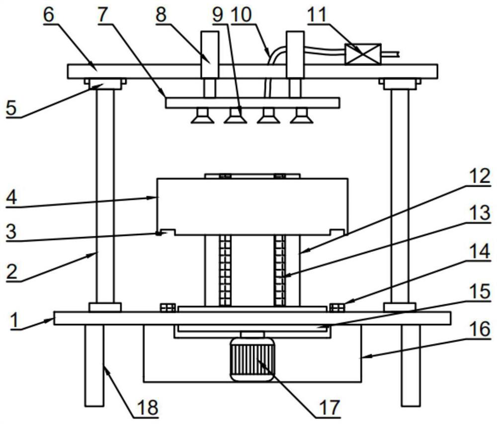
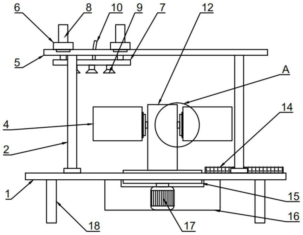
[0025] see figure 1 , 2 And 4, in the embodiment of the present invention, a material receiving device of a polarizer production equipment includes a worktable 1, a support table 16 is installed and fixed on the worktable 1, and a turntable 15 is rotatably installed on the support table 16, And the support table 16 is also provided with a stepping motor 17 for driving the turntable 15 to rotate, the support table 16 is arranged through the work table 1, and a material receiving assembly is also arranged on the supporting table 16, and the material receiving assembly includes: The support table 12 and the material receiving box 4, the supporting table 12 is installed and fixed on the turntable 15, and two sets of second electric guide rails 13 are symmetrically arranged on both sides of the supporting table 12, and the material receiving box 4 passes through the magnetic attraction assembly It is slidably installed on the second electric guide rail 13, and the workbench 1 is a...

Embodiment 2

[0028] see Figures 1 to 6 , the difference between this embodiment and Embodiment 1 is:

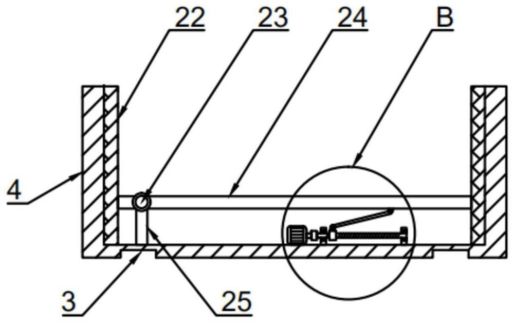
[0029]In this embodiment, a support plate assembly for facilitating the removal of polarizers is also provided in the material receiving box 4 . The support plate assembly includes a support block 25 and a bearing plate 24 , and the support block 25 is installed and fixed on the connecting plate. In the material box 4, one end of the bearing plate 24 is rotatably mounted on the support block 25 through the connecting shaft 23, and the material receiving box 4 is also provided with a screw assembly for driving the bearing plate 24 to rotate on the support block 25. One end of the carrier plate 24 is rotated on the support block 25 with the connecting shaft 23 as the axis to make the other end of the carrier plate 24 tilt up. It is convenient for the staff to carry and use.

[0030] The screw assembly includes a screw 27 and a screw slider 28, the screw 27 is rotatably installed in the m...


PUM


Abstract

The invention discloses a material splicing device of a polarizer production equipment, comprising a worktable, a support table is installed and fixed on the worktable, a turntable is rotatably installed on the support table, and a material receiving table is also arranged on the support table The material receiving assembly includes a support table and a material receiving box, two transport guide rails for transporting the material receiving box are also provided on the worktable, and the material receiving box is also provided with a transport guide rail for use Four sets of support rods are also installed and fixed on the worktable, and first electric guide rails are installed on the two sets of support rods parallel to the transport guide rails, which are slidably installed on the first electric guide rails. There is a fixing plate, several groups of hydraulic cylinders are arranged on the fixing plate, and a feeding plate is installed and fixed on the ejecting end of the hydraulic cylinder. The invention has novel structure and functions, and can effectively improve the production efficiency of polarizers.

Description

technical field [0001] The invention relates to the technical field of polarizer production, in particular to a material splicing device for polarizer production equipment. Background technique [0002] The full name of polarizer is polarizer. The imaging of liquid crystal display must rely on polarized light. All liquid crystals have two polarizers on the front and back of the liquid crystal glass, forming a liquid crystal with a total thickness of about 1mm. If any one is missing Polarizers and liquid crystals cannot display images. Polarizers should be stored at room temperature, and the humidity should be below 75%. It should be stored in a flat position. When stacking, every 300 sheets should be stacked separately and supported. Too much stacking will easily cause damage to the polarizer. [0003] Most of the splicing devices of the existing polarizer production equipment only have a simple stacking function. When the splicing device stacks more than 300 polarizers, ma...

Claims


Application Information

Patent Timeline
Patent Type & Authority Patents(China)
IPC IPC(8): B65G47/90B65G35/00
CPCB65G47/90B65G35/00
Inventor 陈运万富斌
Owner 深圳市运宝莱光电科技有限公司
Why Eureka
Try Eureka