A comber roller

A combing machine and combing technology, applied in the direction of combing machine, textile and papermaking, fiber processing, etc., can solve the problems of inconvenient disassembly, large volume, and low degree of automation, so as to avoid inconvenience, reduce the difficulty of disassembly, and improve automation. degree of effect

Active Publication Date: 2022-05-13
DONGTAI RUNSHENG TEXTILE MACHINERY ACCESSORIES CO LTD
View PDF0 Cites 0 Cited by
  • Summary
  • Abstract
  • Description
  • Claims
  • Application Information

AI Technical Summary

Problems solved by technology

[0003] The purpose of the present invention is to provide a combing machine roller to solve the problem that the existing combing machine roller proposed in the above-mentioned background technology is relatively large and heavy, is not easy to disassemble, and is easy to cause yarn to be wound from both sides of the roller into the drive shaft and with less automation

Method used


Image

  • A comber roller
  • A comber roller
  • A comber roller

Examples


Embodiment Construction

[0030] The following will clearly and completely describe the technical solutions in the embodiments of the present invention with reference to the accompanying drawings in the embodiments of the present invention. Obviously, the described embodiments are only some, not all, embodiments of the present invention. Based on the embodiments of the present invention, all other embodiments obtained by persons of ordinary skill in the art without making creative efforts belong to the protection scope of the present invention.

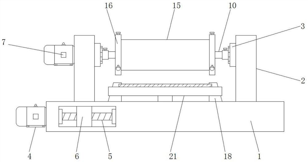
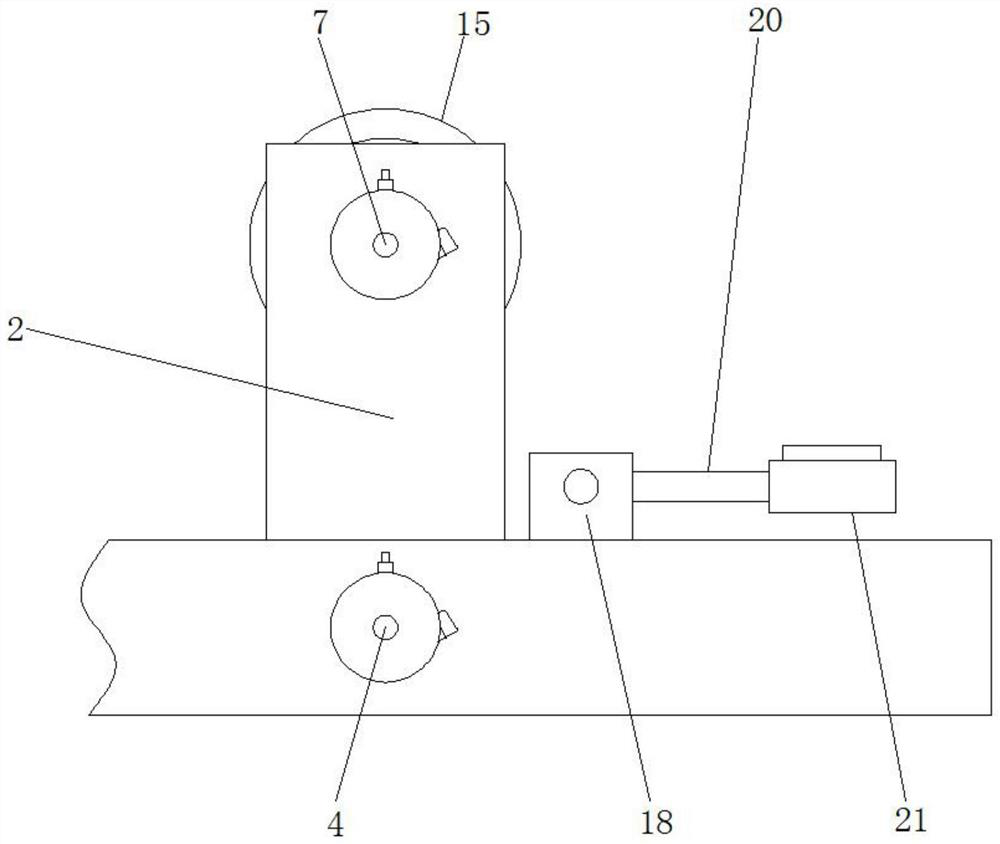
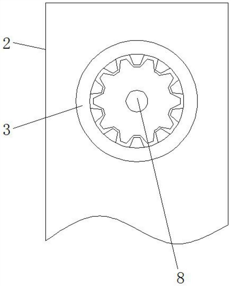
[0031] see Figure 1-7 , the present invention provides a technical solution: a comber roller, such as figure 1 , figure 2 , image 3 and Figure 4 As shown, the two ends of the surface of the comber frame 1 are provided with a mounting frame 2, and the inner surface of the mounting frame 2 is rotatably connected with an internal gear 3, and the left side of the comber frame 1 is fixed with a first motor 4, The output end of the first motor 4 is connected...


PUM


Abstract

The invention discloses a combing machine roller, which comprises a combing machine frame, a limit assembly, a roller cylinder and a rotating assembly, two ends of the surface of the combing machine frame are provided with installation frames, and the first motor The output end of the roller is connected to the screw rod, the movable ring is connected to the surface of the threaded block in rotation, the roller cylinder is arranged on the outside of the support assembly, and the surface of the roller cylinder is provided with cotton baffles at both ends, the first The second gear is rotatably connected to the midpoint surface of the rotating shaft, and the outer side of the second gear is engaged with a rack. The combing machine roller is provided with a threaded block and an arc-shaped plate. By rotating the threaded block at both ends of the cross bar, the threaded block moves backward in the thread groove and slides, so as to drive the movable ring to move backward, and cooperate with the movable rod on the surface of the movable ring. The three groups of arc-shaped plates can be driven to shrink so as to disassemble the cylinder of the roller, so that the overall volume and weight can be reduced, which is beneficial to the maintenance of the cylinder of the roller and improves the practicality.

Description

technical field [0001] The invention relates to the related technical field of textile equipment, in particular to a comber roller. Background technique [0002] Roller is a cylindrical rotating part used in textile machinery for feeding, drafting, output, etc. It is divided into drafting roller, feeding roller, pressing roller, working roller, etc. according to its function. Most of the existing combing machine rollers are integrated, large and heavy, and inconvenient to disassemble, and because the rollers are in a rotating state during use, it is easy to wind the yarn from both sides of the rollers to the drive shaft , and in order not to affect the follow-up use after use, the remaining yarn on the roller surface needs to be cleaned up, while the existing comber rollers are mostly cleaned manually, which is cumbersome to use and has a low degree of automation. Contents of the invention [0003] The purpose of the present invention is to provide a combing machine rolle...

Claims


Application Information

Patent Timeline
Patent Type & Authority Patents(China)
IPC IPC(8): D01G19/18D01G19/22
CPCD01G19/18D01G19/22
Inventor 潘涛
Owner DONGTAI RUNSHENG TEXTILE MACHINERY ACCESSORIES CO LTD
Why Eureka
Try Eureka