Cotton yarn fastening device for warp yarn sizing of textile fabric
A warp sizing and fastening device technology is applied in the field of cotton yarn fastening devices for warp sizing of textile fabrics, and achieves the effect of reasonable design and efficient sizing
- Summary
- Abstract
- Description
- Claims
- Application Information
AI Technical Summary
Problems solved by technology
Method used
Image
Examples
Embodiment 1
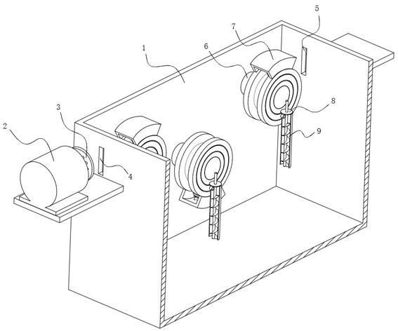
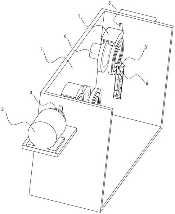
[0027] refer to Figure 1-4 , a cotton yarn fastening device for warp yarn sizing of textile fabrics, including a sizing box 1 with sizing inside and an external winding device for winding cotton yarns. The electric motor 2, and the winding device is arranged on the other side of the sizing box 1, so that it is convenient to straighten the cotton yarn to be sized.
[0028] Secondly, the motor 2 and the winding device are respectively arranged on the outer walls of both sides of the sizing box 1, and the same cotton yarn is connected between the motor 2 and the winding device.
[0029] The following points are worth noting:
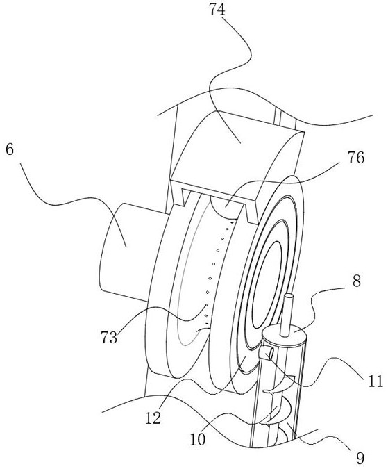
[0030] 1. The cotton yarn runs through the sizing box 1 through the thread inlet hole 4 and the thread outlet hole 5 on the side wall of the sizing box 1, and the cotton yarn in the sizing box 1 is wound on the surface of the sizing pulley 7, so that in the process of winding the cotton yarn, the dragged The cotton yarn will roll with the wound sizing pu...
Embodiment 2
[0038] refer to Figure 5-6The output end of the motor 2 is fixedly connected with a winch reel 3 for selecting the number of twisted wires, and the winch reel 3 includes a rotating disc 31, a plurality of circular plates 32, a plurality of sliding strip holes 33, a plurality of pay-off holes 34, rotating Axle 35, polygonal block 36, a plurality of magnetic blocks 37, a plurality of pulling springs 38 and a plurality of clamping blocks 39, a plurality of sliding bar holes 33 are circumferentially arranged on the rotating disk 31, and the circular plate 32 passes through the threading cylinder The rotating disc 31 slides along the sliding strip hole 33 , one end of the rotating shaft 35 is fixedly connected to the output end of the motor 2 , and the other end of the rotating shaft 35 is fixedly connected to the rotating disc 31 through a polygonal block 36 .
[0039] The following points are worth noting:
[0040] 1. The magnetic block 37 is sleeved on the threading cylinder, ...
PUM
 Abstract
Description
Claims
Application Information
 - R&D
- Intellectual Property
- Life Sciences
- Materials
- Tech Scout
- Unparalleled Data Quality
- Higher Quality Content
- 60% Fewer Hallucinations
Browse by: Latest US Patents, China's latest patents, Technical Efficacy Thesaurus, Application Domain, Technology Topic, Popular Technical Reports.
© 2025 PatSnap. All rights reserved.Legal|Privacy policy|Modern Slavery Act Transparency Statement|Sitemap|About US| Contact US: help@patsnap.com


