Combustion chamber

A combustor, gas turbine technology, which is applied in the fields of hot gas side, cold gas side and hot gas side and method, can solve problems such as low efficiency

Active Publication Date: 2021-09-14
西门子能源全球有限两合公司
View PDF16 Cites 0 Cited by
  • Summary
  • Abstract
  • Description
  • Claims
  • Application Information

AI Technical Summary

Problems solved by technology

However, the greater the volume flow of cooling air used to protect the metal parts, the lower the efficiency

Method used


Image

  • Combustion chamber
  • Combustion chamber
  • Combustion chamber

Examples


Embodiment Construction

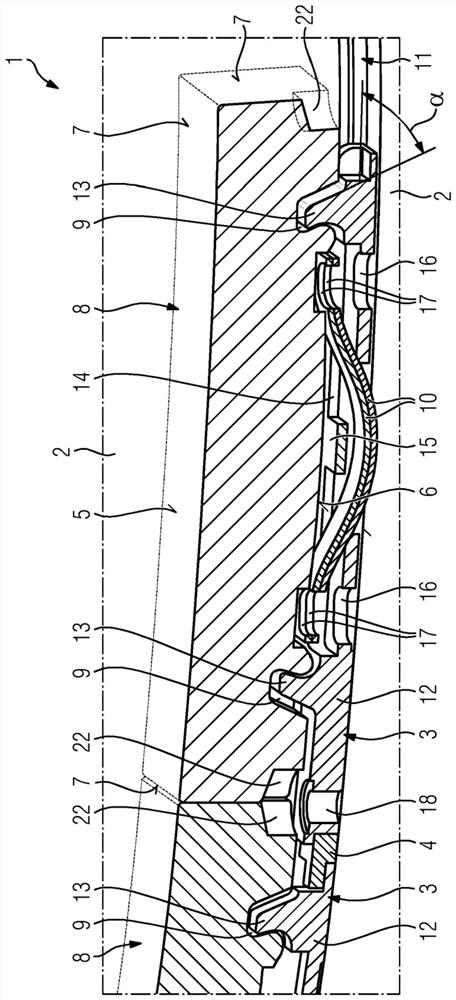
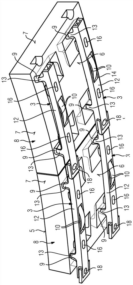
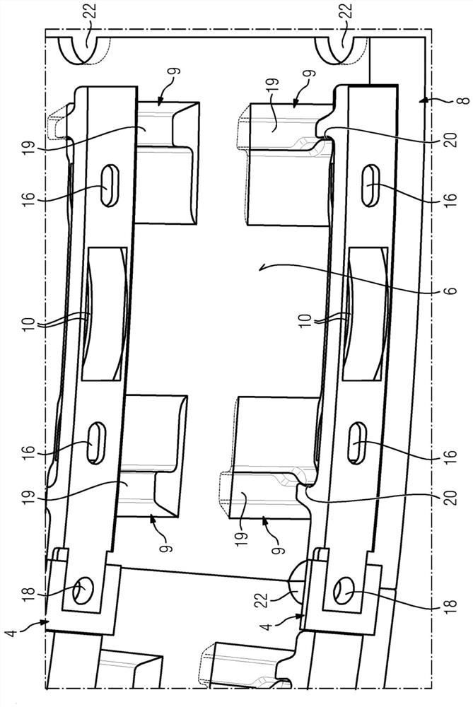
[0032] Figure 1 to Figure 6A combustion chamber 1 according to an embodiment of the invention is shown, which in the present case is a combustion chamber of a gas turbine. The combustion chamber 1 comprises: a load-bearing structure 2; a plurality of holding elements 3 fastened on the load-bearing structure 2; a plurality of connecting elements 4 interconnecting the holding elements 3 arranged adjacently in the circumferential direction U; a plurality of Heat shield elements 8 which together form a heat shield, each having a hot gas side 5 , a cold gas side 6 and an end side 7 connecting the hot gas side 5 and the cold gas side 6 to one another, wherein the holding element 3 Form-fittingly engages in a recess 9 provided on the heat shielding element 8; and a spring element 10 extending between the carrier structure 2 and the heat shielding element 8, held on the holding element 3, the spring Elements are currently available in the form of wave-bent leaf springs.

[0033] Th...


PUM


Abstract

The invention relates to a combustion chamber (1), in particular a combustion chamber of a gas turbine, comprising a support structure (2), a plurality of retaining elements (3) fastened to the support structure (2), and a plurality of heat shield elements (8) which jointly form a heat shield and which each comprise a hot gas side (5), a cold gas side (6) and end faces (7) which interconnect the hot gas side (5) and the cold gas side (6), the retaining elements (3) interlockingly engaging in recesses (9) in the heat shield elements (8), characterized in that the retaining elements (3) each comprise at least two engagement portions (13) for interlockingly engaging in the recesses (9) in a heat shield element (8), which engagement portions are interconnected in a tensionally rigid manner and are tensionally rigid themselves, and in that spring elements (10) extend between the support structure (2) and the heat shield elements (8), which spring elements are designed in particular as leaf springs and effect a frictional connection between the engagement portions (13) of the retaining elements (3) and the heat shield elements (8).

Description

technical field [0001] The invention relates to a combustor, in particular a combustion chamber of a gas turbine, having a carrier structure, a plurality of holding elements fastened to the carrier structure and a plurality of heat shield elements which together form a heat shield, the heat shield The elements each have a hot gas side, a cold gas side and an end side connecting the hot gas side and the cold gas side to each other, wherein the retaining element engages in a form-fitting manner in a recess provided on the heat shield element. Furthermore, the invention relates to a device and a heat shield element for realizing such a combustion chamber. Background technique [0002] Due to the high temperatures present during operation, for example the combustion chamber of a gas turbine is provided with a heat shield which protects the housing wall of the combustion chamber from the hot atmosphere in the combustion space of the combustion chamber. A heat shield capable of r...

Claims


Application Information

Patent Timeline
Patent Type & Authority Applications(China)
IPC IPC(8): F23R3/00F23R3/60F23M5/04
CPCF23R3/002F23R3/60F23R2900/00005F23R2900/00017F23M5/04
Inventor 马蒂亚斯·格拉尔基克劳斯·克鲁施丹尼尔·施密特
Owner 西门子能源全球有限两合公司
Why Eureka
Try Eureka