Environment-friendly intelligent building

An intelligent building and environmental protection technology, applied in the direction of buildings, building structures, drainage structures, etc., can solve the problems of no protective measures on the roof, dangerous watering treatment, plant death, etc., to improve the scope of watering and cooling, avoid trouble and Dangerous, effect of avoiding high temperature death

Inactive Publication Date: 2021-09-17
李勇超
View PDF0 Cites 1 Cited by
  • Summary
  • Abstract
  • Description
  • Claims
  • Application Information

AI Technical Summary

Problems solved by technology

[0003] However, in the actual planting process, we found that due to the high roof, it is extremely inconvenient when we need to water the vegetation, and some roofs have no protective measures, so watering is extremely dangerous. plants, which causes the sun's rays to fall directly on the plants, and in warmer weather, the heat of the sun can cause the plants to die

Method used


Image

  • Environment-friendly intelligent building
  • Environment-friendly intelligent building
  • Environment-friendly intelligent building

Examples


Embodiment 1

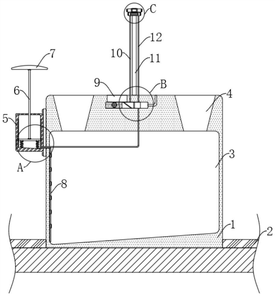
[0030] refer to Figure 1-6 , an environmentally friendly intelligent building, comprising a water collection tank 1 arranged on the roof, a planting area 2 is arranged on the roof, a water collection chamber 3 and an adjustment chamber 16 are arranged in the water collection tank 1, and the adjustment chamber 16 is located in the water collection chamber 3 Above, two water inlets 4 are provided on the inner top of the water collection chamber 3, the inner bottom surface of the water collection chamber 3 is inclined, and the height of the left end of the slope is lower than the height of the right end, and a pressure storage box is installed on the left side of the water collection tank 1 5;

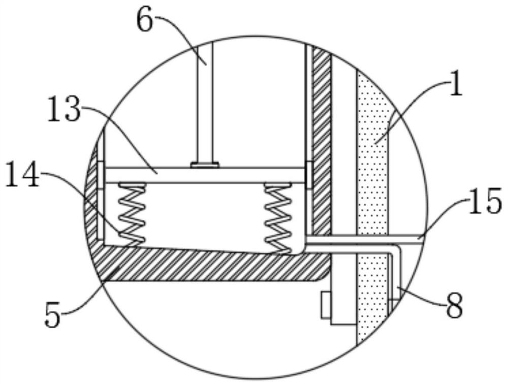
[0031] The pressure accumulation box 5 is provided with a pressure accumulation mechanism, the pressure accumulation mechanism includes a pressure accumulation plate 13 arranged in the pressure accumulation box 5, the lower end of the pressure accumulation plate 13 is elastically connect...

Embodiment 2

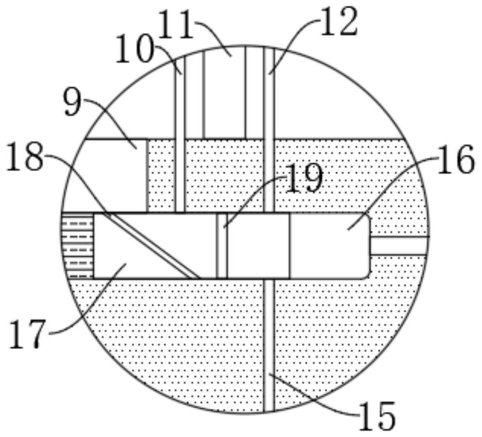
[0040] refer to Figure 7-10 The difference between this embodiment and Embodiment 1 is that both the watering nozzle 20 and the atomizing nozzle 21 are ring-shaped, and are slidably connected with the vertical rod 11, and the upper end of the atomizing nozzle 21 is fixedly connected with the lower end of the watering nozzle 20, Both sides of the vertical rod 11 are provided with guide grooves 25, and the inner side of the watering nozzle 20 is symmetrically fixedly connected with a guide block 26 that matches the two guide grooves 25. The setting of the guide block 26 and the guide groove 25 can ensure that the watering nozzle 20 and The atomizing nozzle 21 moves up and down smoothly, the second airbag 24 is installed between the lower end of the atomizing nozzle 21 and the upper end of the water collecting tank 1, and the first airbag 22 is arranged between the pressure accumulator plate 13 and the inner top of the pressure accumulator box 5. One airbag 22 communicates with ...


PUM


Abstract

The invention discloses an environment-friendly intelligent building. The environment-friendly intelligent building comprises a water collecting tank arranged on a roof, a planting area is arranged on the roof, a water collecting cavity and an adjusting cavity are formed in the water collecting tank, the adjusting cavity is located above the water collecting cavity, two water inlets are formed in the inner top of the water collecting cavity, and a pressure storage box is installed on the left side of the water collecting tank; a pressure storage mechanism is arranged in the pressure storage box and comprises a pressure storage plate arranged in the pressure storage box, the lower end of the pressure storage plate is elastically connected with the inner bottom of the pressure storage box through two pressure storage springs, and the upper end of the pressure storage plate is fixedly connected with a connecting rod. When the building is used, green plants can be planted on the roof of the building, so that the purpose of reducing urban greenhouse gas emission is achieved, vegetation on the roof can be automatically watered, meanwhile, in high-temperature weather, the area where the plants are located can be cooled, and normal growth of the plants is facilitated.

Description

technical field [0001] The invention relates to the field of intelligent buildings, in particular to an environment-friendly intelligent building. Background technique [0002] With the continuous development of the times, the awareness of environmental protection has gradually penetrated into the hearts of the people. In today's life, in order to reduce the increase in greenhouse gases, some cities will increase the planting rate of vegetation, especially the roofs of some buildings. Larger, it is a good choice for planting green plants, and slowly green roofs are gradually integrated into our lives; [0003] However, in the actual planting process, we found that due to the high roof, it is extremely inconvenient when we need to water the vegetation, and some roofs have no protective measures, so watering is extremely dangerous. plants, which causes the sun's rays to fall directly on the plants, and in warmer weather, the heat of the sun can cause the plants to die. Cont...

Claims


Application Information

Patent Timeline
Patent Type & Authority Applications(China)
IPC IPC(8): A01G9/033A01G27/00E03B3/02E03F5/10E04D13/00F24F5/00
CPCA01G9/033A01G27/008E04D13/00E03B3/02E03F5/10F24F5/0092Y02A20/108
Inventor 李勇超
Owner 李勇超
Why Eureka
Try Eureka