Novel rotating shaft structure for draw-bar box

A technology of rotating shaft structure and trolley case, which is applied in applications, travel goods, clothing, etc., can solve the problems of high cost and achieve the effects of prolonging service life, firm installation, and convenient assembly

Pending Publication Date: 2021-09-17
广东铭恒供应链有限公司
View PDF0 Cites 0 Cited by
  • Summary
  • Abstract
  • Description
  • Claims
  • Application Information

AI Technical Summary

Problems solved by technology

[0004] The purpose of the present invention is to provide a new type of rotating shaft structure for trolley case, so as to solve the problem that the entire rotating shaft structure needs to be replaced when some parts of the rotating shaft structure are damaged in the above-mentioned background technology, and the cost is relatively high

Method used


Image

  • Novel rotating shaft structure for draw-bar box
  • Novel rotating shaft structure for draw-bar box
  • Novel rotating shaft structure for draw-bar box

Examples


Embodiment Construction

[0020] The following will clearly and completely describe the technical solutions in the embodiments of the present invention in conjunction with the accompanying drawings in the embodiments of the present invention. Based on the embodiments of the present invention, those skilled in the art can obtain All other embodiments of all belong to the protection scope of the present invention.

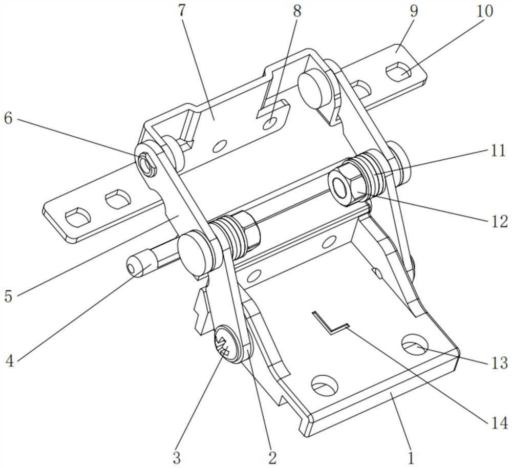
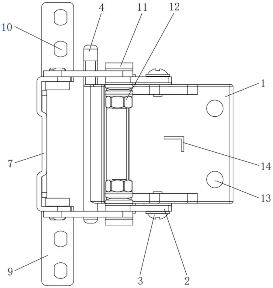
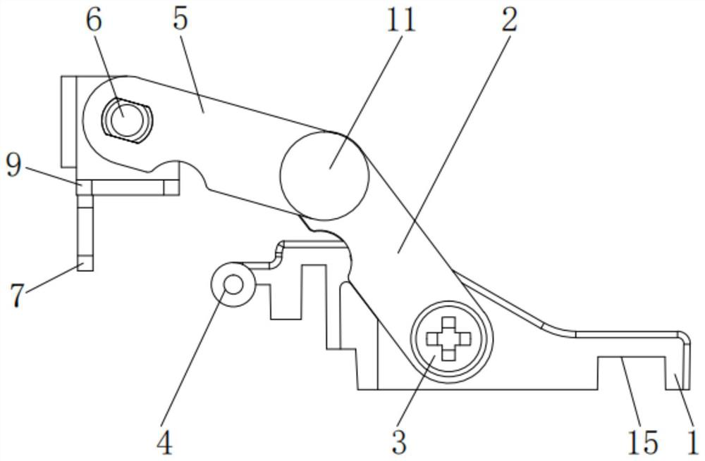
[0021] see Figure 1-4 , an embodiment provided by the present invention: a new shaft structure for a trolley case, including a first connecting piece 1, a first side connecting piece 2, a second side connecting piece 5, a second connecting piece 7 and a first installation Holes 13, one side of the surface of the first connector 1 is provided with first mounting holes 13, and the first mounting holes 13 have a symmetrical structure;

[0022] Both sides of the first connecting piece 1 are provided with a first side connecting piece 2, and the first side connecting piece 2 is rotatably connect...


PUM


Abstract

The invention discloses a novel rotating shaft structure for draw-bar box. The rotating shaft structure comprises a first connecting piece, first side connecting sheets, second side connecting sheets, a second connecting piece and first mounting holes, one side of the surface of the first connecting piece is provided with the first mounting holes, the two sides of the first connecting piece are provided with the first side connecting sheets, the first side connecting pieces are rotationally connected with the first connecting piece through first connecting bolts, second connecting pieces are arranged on one side of the first connecting piece, second mounting holes are formed in the surfaces of the second connecting pieces, second side connecting pieces are arranged on the side, close to the first connecting piece, of the second connecting piece, and the second side connecting pieces are rotationally connected with the second connecting piece through the second connecting bolts. The rotating shaft structure is more convenient to assemble, parts in the structure can be replaced at will, the use cost is saved, the stability of the rotating shaft structure is improved, the rotating shaft structure has the advantages of being high in hardness, resistant to abrasion and corrosion, and the service life is prolonged.

Description

technical field [0001] The invention relates to the technical field of trolley cases, in particular to a novel rotating shaft structure for a trolley case. Background technique [0002] The trolley case refers to a suitcase with a trolley and a roller. It is widely used because of its convenience. It is divided into pipes to facilitate dragging when walking and greatly reduce the burden. The rotating shaft of the trolley case is one of the main parts of the trolley case. [0003] There are many kinds of such shaft structures on the market today, which can basically meet people's needs, but there are still some shortcomings. The existing shaft structures are generally composed of integrated structures, which are not only not convenient enough to assemble, but also When some parts are damaged, the entire rotating shaft structure needs to be replaced, and the cost is relatively large, so it needs to be improved. Contents of the invention [0004] The purpose of the present ...

Claims


Application Information

Patent Timeline
Patent Type & Authority Applications(China)
IPC IPC(8): A45C13/00
CPCA45C13/001
Inventor 李建锋
Owner 广东铭恒供应链有限公司
Why Eureka
Try Eureka