
Strip winding drum

A reel and strip technology, which is applied in the coiling (uncoiling) field of aluminum strips and thin strips, can solve problems such as easy leakage of expansion and contraction cylinders, troublesome replacement of seals, jamming of axial wedges, etc., and achieve shortening Disassembly and assembly cycle, easy processing, and stable structure

Pending Publication Date: 2021-09-17
湖南科美达重工有限公司
View PDF0 Cites 1 Cited by
  • Summary
  • Abstract
  • Description
  • Claims
  • Application Information

AI Technical Summary

Problems solved by technology

[0004] One: The expansion and contraction of the reel uses the expansion and contraction oil cylinder as the power source. The expansion and contraction oil cylinder is prone to leakage. It is very troublesome to disassemble and replace the seal on site. The on-site disassembly and assembly takes a long time and maintenance is troublesome.
[0005] Two: The expansion and contraction of the reel adopts the configuration of expansion and contraction oil cylinder, tie rod and copper sleeve. When the reel expands, the piston rod of the oil cylinder pulls the pull rod to move in the copper sleeve. cartridge not working
[0006] Three: The axial wedge moves axially in the groove of the main shaft. When the non-ferrous metal aluminum strip is coiled, the aluminum strip will produce a lot of powder during the coiling process, and the powder enters the sliding groove of the axial wedge and lubricating grease After mixing, the axial wedge will be blocked, and the reel needs to be disassembled regularly for internal cleaning. In severe cases, the wedge will be broken directly, resulting in low production efficiency
[0007] Four: complex structure, high manufacturing precision, long cycle, high cost and high maintenance cost

Method used


Image

  • Strip winding drum
  • Strip winding drum
  • Strip winding drum

Examples


Embodiment Construction

[0032] The following will clearly and completely describe the technical solutions in the embodiments of the present invention with reference to the accompanying drawings in the embodiments of the present invention. Obviously, the described embodiments are only some, not all, embodiments of the present invention. All other embodiments obtained by persons of ordinary skill in the art based on the embodiments of the present invention belong to the protection scope of the present invention.

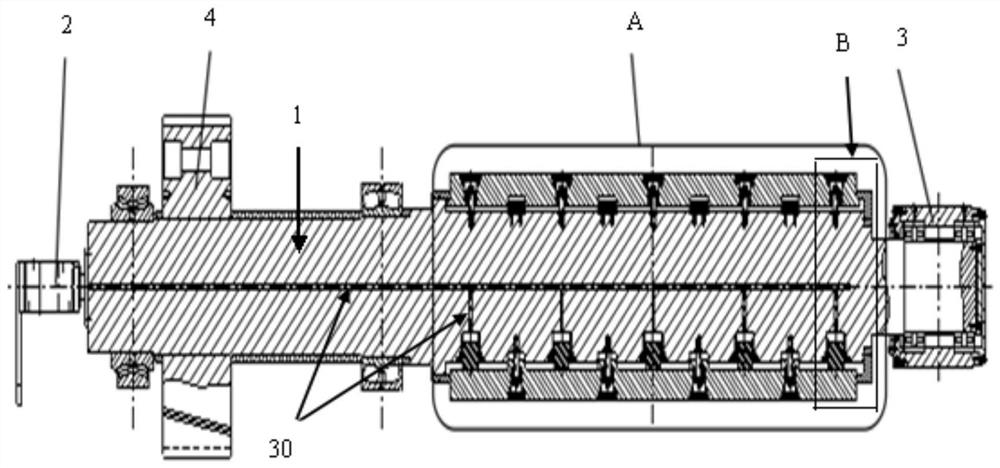
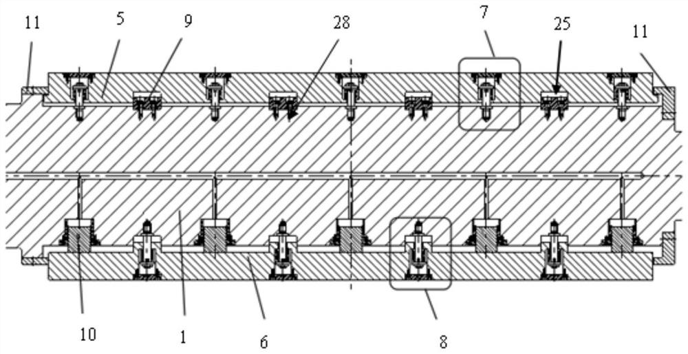
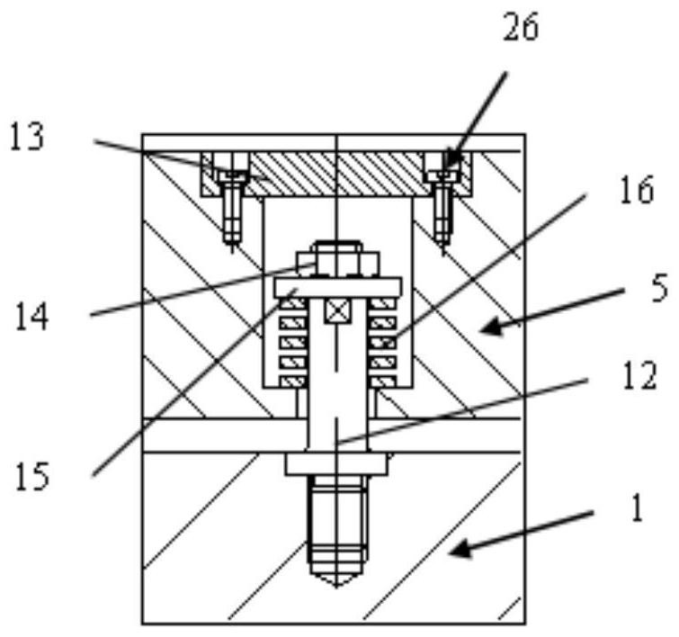
[0033] Such as Figure 1-8 As shown, a strip reel according to the embodiment of the present invention includes a main shaft 1, the left end of the main shaft 1 is rotatably connected with a swivel joint 2, and the right end of the main shaft 1 is connected with a head support 3, so The left part of the main shaft 1 is connected with a gear assembly 4, and the right part of the main shaft 1 is respectively connected with a fan-shaped plate 5 and a radial wedge 6 through a fan-shaped plate con...


PUM


Abstract

The invention discloses a strip winding drum. The strip winding drum comprises a main shaft, the left end face of the main shaft is rotationally connected with a rotating connector, the right end face of the main shaft is connected with a head supporting piece, the left portion of the main shaft is connected with a gear assembly, and the right portion of the main shaft is connected with a fan-shaped plate and a radial inclined wedge through a fan-shaped plate connecting assembly and a wedge connecting assembly; and protection blocks are arranged at the two ends of the fan-shaped plate, a guide key is arranged between the main shaft and the fan-shaped plate, and a radial oil cylinder is arranged between the main shaft and the radial inclined wedge. According to the strip winding drum, the overall structure is compact, the number of conventional quick-wear parts is small, safety and reliability are achieved, assembling is easy, the production cycle is shortened to a great extent, and the maintenance and manufacturing cost is reduced to a great extent.

Description

technical field [0001] The invention relates to the technical field of coiling (uncoiling) of aluminum strips and thin strips, in particular to a strip reel. Background technique [0002] At present, under the existing technology, the coiling of aluminum strip and thin strip mainly adopts the closed wedge structure of the cold rolling reel, such as Figure 9-10 As shown, it is mainly composed of sector plate, main shaft, tie rod, extension shaft, axial wedge, radial wedge, crosshead, head support component, expansion and contraction cylinder (with rotary joint), gear transmission components, etc. The expansion and contraction cylinder (with rotary joint) is connected to the main shaft through the flange, the piston rod of the expansion and contraction cylinder is directly connected to the tie rod through the thread, the tie rod is connected to the axial wedge through the cross head, and the axial wedge is connected to the radial wedge through the inclined surface , the radia...

Claims


Application Information

Patent Timeline
Patent Type & Authority Applications(China)
IPC IPC(8): B21C47/30B21C47/02
CPCB21C47/30B21C47/02
Inventor 余峰邓立群司马攀峰吴久福胡世标徐天佑徐卫林
Owner 湖南科美达重工有限公司
Learn More