Pipeline assembly fixing equipment for steel structure truss

A technology for pipe components and fixed equipment, applied in welding equipment, auxiliary welding equipment, metal processing equipment, etc., can solve the problems of large size error of ring-shaped steel pipe truss, affecting the use value of truss, and high labor intensity of staff

Active Publication Date: 2021-09-17
THE THIRD CONSTR OF CHINA CONSTR EIGHTH ENG BUREAU
View PDF7 Cites 0 Cited by
  • Summary
  • Abstract
  • Description
  • Claims
  • Application Information

AI Technical Summary

Problems solved by technology

[0004] 1. In the existing manufacturing of ring-shaped steel pipe trusses, there is no good equipment for fixing and clamping ring-shaped steel pipe trusses. Basically, each section of arc-shaped steel pipes is placed manually, Position calibration, butt joints between each section of arc-shaped steel pipes, and welding installation of square support frames will not only bring greater labor intensity to the staff, but also cause large dimensional errors for the manufactured ring-shaped steel pipe trusses, seriously affecting Affect the use value of the truss;
[0005] 2. When the existing ring-shaped steel pipe trusses are manufactured, it is difficult to adjust the distance between each arc-shaped steel pipe anytime and anywhere according to the actual production, and the operating site conditions are varied when making ring-shaped steel pipe trusses. However, the existing It is difficult to adjust the operating position of the welded square support frame on the arc-shaped steel pipe at any time according to the situation of the operation site with the fixed clamping equipment, resulting in a decrease in the production efficiency of the ring-shaped steel pipe truss

Method used


Image

  • Pipeline assembly fixing equipment for steel structure truss
  • Pipeline assembly fixing equipment for steel structure truss
  • Pipeline assembly fixing equipment for steel structure truss

Examples


Embodiment Construction

[0032] In order to make the technical means realized by the present invention, creative features, goals and effects easy to understand, the following combination Figure 1 to Figure 8 , to further elaborate the present invention.

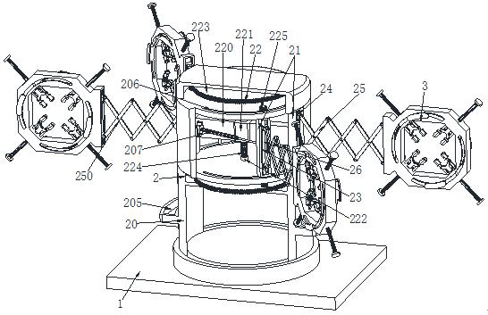
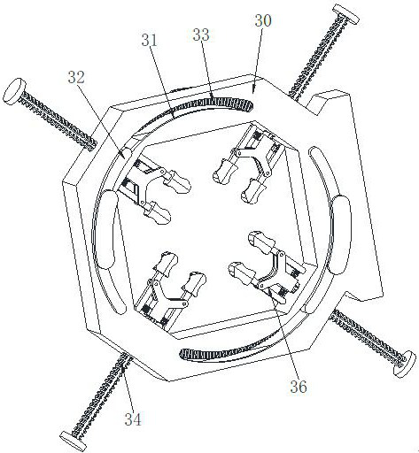
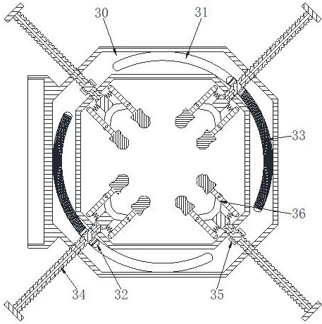
[0033] A pipe component fixing device for a steel structure truss, comprising a base 1, an adjusting device 2 and a fixing device 3, the upper surface of the base 1 is provided with an adjusting device 2, and the adjusting device 2 is provided with a fixing device 3; wherein:

[0034]The adjusting device 2 includes an adjusting bracket 20, an adjusting pillar 21, an adjusting unit 22, an adjusting chute 23, an adjusting slider 24, an adjusting connecting rod 25 and an adjusting screw 26. The upper surface of the base 1 is provided with an adjusting bracket 20, and the adjusting bracket 20, two pairs of adjusting pillars 21 are evenly arranged along the circumferential direction at the edge between the upper and lower bottom plates, and an adjusting ...


PUM


Abstract

The invention relates to pipeline assembly fixing equipment for a steel structure truss. The pipeline assembly fixing equipment for the steel structure truss comprises a base, an adjusting device and a fixing device, the adjusting device is arranged on the upper surface of the base, and the fixing device is arranged on the adjusting device. According to the pipeline assembly fixing equipment for the steel structure truss, the current problems that no good equipment special for fixing and clamping in the annular steel pipe truss manufacturing process exists, basically, position placement, position calibration, butt joint between every two arc-shaped steel pipes and welding installation of a square supporting frame are manually carried out on each arc-shaped steel pipe, in this way, large labor intensity is brought to workers, and the size error of the manufactured annular steel pipe truss is large; and the distance between every two arc-shaped steel pipes is difficult to adjust anytime and anywhere according to actual manufacturing, and the existing fixing and clamping equipment is difficult to adjust the operation position of the square supporting frame welded on the arc-shaped steel pipes at any time according to the condition of an operation site can be solved.

Description

technical field [0001] The invention relates to the field of truss manufacture, in particular to a pipe assembly fixing device for steel structure trusses. Background technique [0002] Steel pipe truss refers to a lattice structure composed of round rods connected to each other at the ends. The trusses make the truss structure economical in materials and light in weight, and are easy to form various shapes to suit different purposes. For example, it can be made simply Trusses, arches, frames and towers etc. Compared with the grid structure, the steel pipe truss structure saves the lower chord longitudinal members and the ball joints of the grid, which can meet the requirements of various architectural forms, especially the construction of round arches and arbitrary curved shapes has more advantages than the grid structure. It has the same stability and saves the amount of materials. The steel pipe truss structure is developed on the basis of the grid structure. Compared wi...

Claims


Application Information

Patent Timeline
Patent Type & Authority Applications(China)
IPC IPC(8): B23K37/04
CPCB23K37/0435Y02E10/50
Inventor 张鑫赵惟诚张向顺李培培范金鹏
Owner THE THIRD CONSTR OF CHINA CONSTR EIGHTH ENG BUREAU
Why Eureka
Try Eureka