Full-automatic assembling equipment for environment-friendly rotor

A fully automatic technology for assembly equipment, applied in metal processing equipment, devices for coating liquid on surfaces, metal processing, etc. It can solve the problems of inability to operate manually, cause great harm to human body, and low work efficiency, and achieve good market application value. , The effect of less harm to human body and high work efficiency

Inactive Publication Date: 2021-09-17
深圳市阿尓法智慧科技有限公司 +1
View PDF0 Cites 0 Cited by
  • Summary
  • Abstract
  • Description
  • Claims
  • Application Information

AI Technical Summary

Problems solved by technology

[0002] A rotor refers to a rotating body supported by a bearing, an object that does not have a rotating shaft, such as a disc. When it adopts a rigid connection or an additional shaft, it can be regarded as a rotor, and the rotor is used in many places, such as motors, engines, Fans, cars, airplanes, etc. will be used, and most of the existing rotors are processed manually, and the processed products are not environmentally friendly. If they are subsequently used in equipment products, they will also cause environmental problems. However, the environmental protection rotor cannot be manually operated during the processing process, the work efficiency is low, it is not environmentally friendly, it is harmful to the human body, the operation is extremely inconvenient, and the cost is high.

Method used


Image

  • Full-automatic assembling equipment for environment-friendly rotor
  • Full-automatic assembling equipment for environment-friendly rotor
  • Full-automatic assembling equipment for environment-friendly rotor

Examples


Embodiment approach

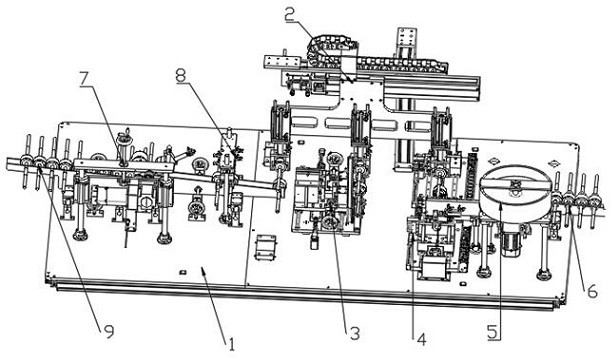
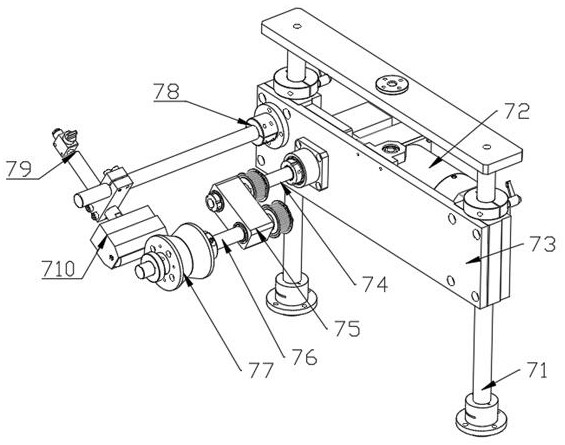
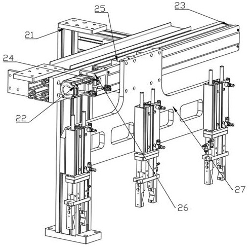
[0026] like Figure 1-Figure 6One of the described embodiments: a fully automatic assembly equipment for an environmental protection rotor, comprising a mounting plate 1, on which are respectively provided an environmental protection oiling device, a transplanting device 2, a circlip device 3, and a material waiting device 4. , the first feeding device 5, the second feeding device and the feeding chute 6, the circlip device 3 is arranged in the upper middle part of the mounting plate 1, the rear side of the circlip device 3 is provided with a transplanting device 2, The left side of the circlip device 3 is provided with an environmental protection oiling device, the right side of the circlip device 3 is provided with a material waiting device 4, and the right side of the material waiting device 4 is provided with a feeding chute 6, and the feeding chute 6 A first feeding device 5 and a second feeding device are respectively provided on both sides, and the environmental protect...

Embodiment 2

[0035] The difference between the second embodiment and the above is that the snap ring device 3 and the environmental protection oiling device are both provided with photoelectric sensors.

Embodiment 3

[0036] The difference between the third embodiment and the above is that the blanking sensor is set as a square functional sensor.


PUM


Abstract

The invention discloses full-automatic assembling equipment for an environment-friendly rotor. The full-automatic assembling equipment comprises a mounting plate, an environment-friendly oil coating device, a transplanting device, a spring clamping device, a material waiting device, a first feeding device, a second feeding device and a discharging sliding way are arranged on the mounting plate, and the spring clamping device is arranged in the middle of the upper portion of the mounting plate. The transplanting device is arranged on the rear side of the spring clamping device, the environment-friendly oil coating device is arranged on the left side of the spring clamping device, the material waiting device is arranged on the right side of the spring clamping device, the discharging sliding way is arranged on the right side of the material waiting device, and the first feeding device and the second feeding device are arranged on the two sides of the discharging sliding way correspondingly. The environment-friendly oil coating device comprises an oil coating assembly, a flow dividing assembly and a conveying assembly, the oil coating device is arranged on one side of the conveying assembly, and the flow dividing assembly is arranged above one end of the conveying assembly. The full-automatic assembling equipment for the environment-friendly rotor is high in working efficiency, low in environment-friendly machining cost and good in market application value.

Description

technical field [0001] The invention relates to the technical field of environmental protection rotor processing, in particular to a fully automatic assembly equipment of an environmental protection rotor. Background technique [0002] A rotor refers to a rotating body supported by a bearing, an object such as an optical disc that does not have its own axis of rotation, when it adopts a rigid connection or an additional axis, it can be regarded as a rotor, and the rotor is used in many places, such as motors, engines, Fans, automobiles, airplanes, etc. will be used, and most of the existing rotors are processed manually, and the processed products are not environmentally friendly. In the process of processing, the environmental protection rotor cannot be operated manually, the work efficiency is low, it is not environmentally friendly, it is harmful to the human body, the operation is extremely inconvenient, and the cost is high. [0003] The prior art has shortcomings and ...

Claims


Application Information

Patent Timeline
IPC IPC(8): B23P19/00B05C5/02
CPCB23P19/00B23P19/001B05C5/02
Inventor 李聪
Owner 深圳市阿尓法智慧科技有限公司
Why Eureka
Try Eureka