Punching equipment for continuous production of disc brushes

A technology of punching equipment and disk brushes, which is applied to cleaning methods and appliances, chemical instruments and methods, cleaning methods using tools, etc., can solve the problems of non-continuous processing and general punching efficiency, and achieve high punching efficiency , Improve the quality of punching and save costs

Active Publication Date: 2021-09-17
安徽环美刷业股份有限公司
View PDF7 Cites 0 Cited by
  • Summary
  • Abstract
  • Description
  • Claims
  • Application Information

AI Technical Summary

Problems solved by technology

However, this device cannot be used for continuous processing, and the drilling efficiency is relatively average.

Method used


Image

  • Punching equipment for continuous production of disc brushes
  • Punching equipment for continuous production of disc brushes
  • Punching equipment for continuous production of disc brushes

Examples


Embodiment 1

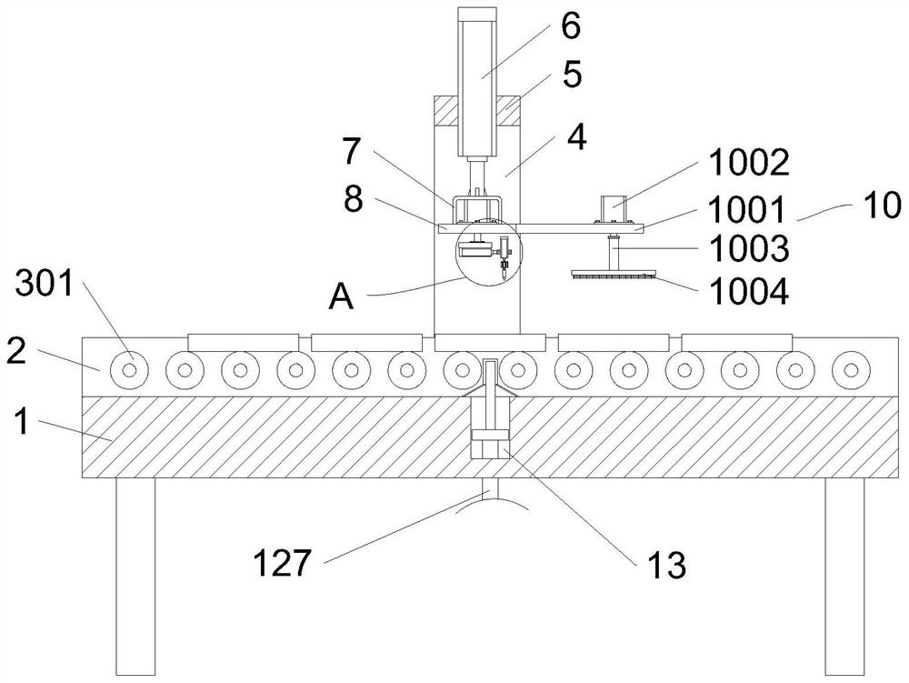
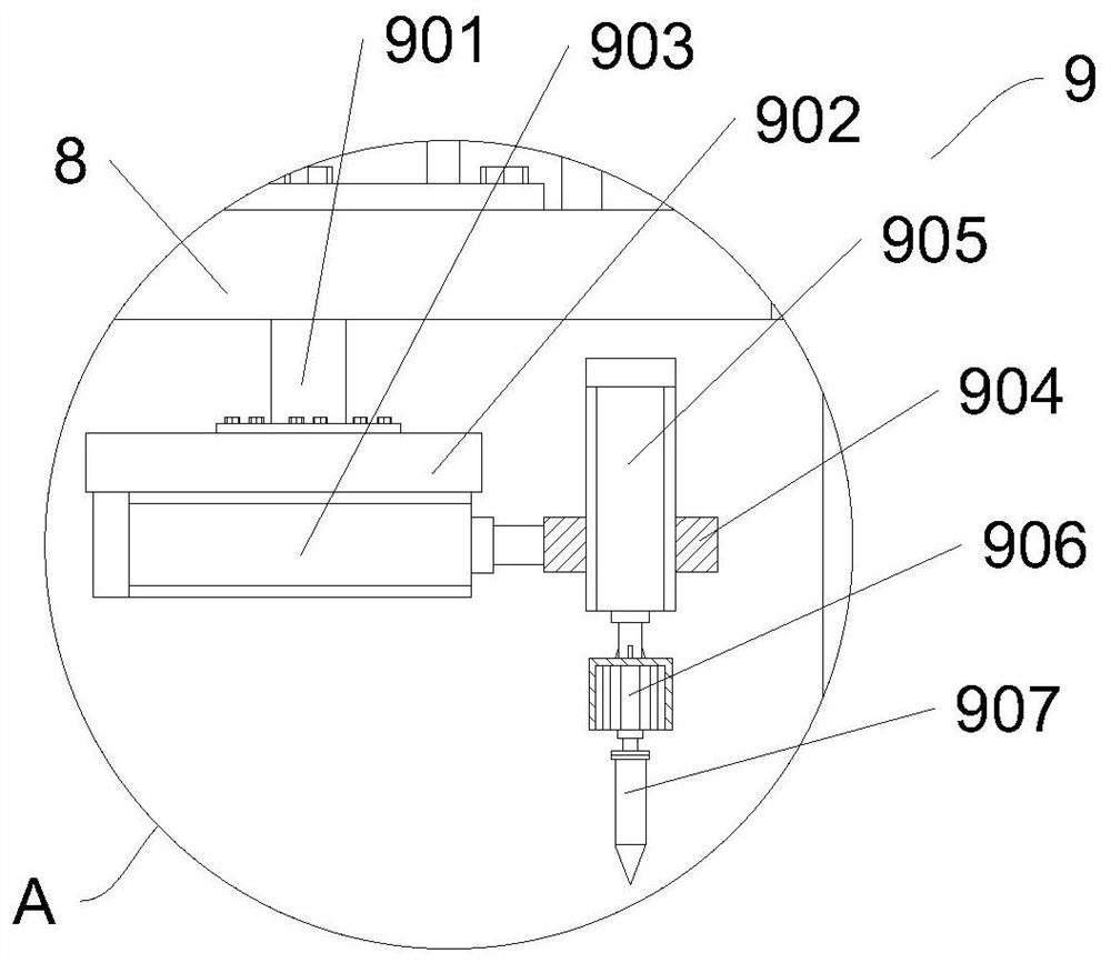
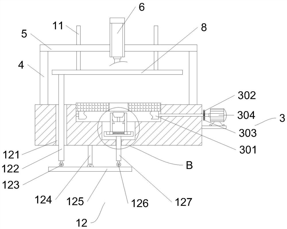
[0031] In this embodiment, as shown in Figure 1-6, a kind of punching equipment for the continuous production of disk brushes includes a workbench 1, and the top of the workbench 1 is provided with a through groove 2 along the horizontal direction, and a useful hole is installed in the through groove 2. The conveying mechanism 3 is used to convey the brush, and the top middle of the workbench 1 corresponds to the front and rear sides of the through groove 2. A horizontal plate 5 is fixed through the vertical plate 4. The middle part of the horizontal plate 5 is fixed with a hydraulic rod 6. The hydraulic rod The telescoping end of a 6 is fixed with a moving plate 8 through the support frame 7, and the top of the moving plate 8 is symmetrically fixed with a limit rod 11 along the front and rear directions. A drilling mechanism 9 for punching the disk brush is provided, and one end of the moving plate 8 along the conveying direction of the conveying mechanism 3 is provided with a...

Embodiment 2

[0034]On the basis of Embodiment 1, the cleaning mechanism 10 includes a support rod 1001 fixed to one end of the moving plate 8 along the conveying direction of the conveying mechanism 3, and the upper position of the support rod 1001 corresponding to the through groove 2 is fixed with a motor four 1002, and a motor four 1002 A rotating shaft 1003 is fixed at the output end of the rotating shaft 1003, and a cleaning brush 1004 is fixed at the bottom of the rotating shaft 1003. The bristle of cleaning brush 1004 adopts wear-resistant plastic material. Through the above method, during the downward movement of the moving plate 8, the cleaning brush 1004 is driven to move down to the surface of the disc brush, the motor 4 1002 is started, the rotating shaft 1003 and the cleaning brush 1004 are driven to rotate, and the waste debris generated by punching is cleaned to avoid waste debris. Accumulated on the surface of the disc brush, it is convenient for the subsequent processing o...

Embodiment 3

[0036] On the basis of Embodiment 2, the transmission mechanism 12 includes a through hole 121 that runs through the workbench 1 and is located at the rear side of the through groove 2, and the bottom end of the moving plate 8 corresponds to the position of the through hole 121 and is vertically fixed with a transmission rod. One 122, the bottom end of the transmission rod one 122 passes through the through hole 121 and is correspondingly abutted against the rotating rod 125 arranged along the front and rear direction, the top middle part of the rotating rod 125 is rotationally connected with the fixed rod 124, and the top of the fixed rod 124 is connected with the workbench The bottom end of 1 is fixed, and the position of the front section of the top of the rotating rod 125 corresponds to the position of the groove 13. The transmission rod 2 127 with a rectangular cross section is correspondingly abutted. The top of the transmission rod 127 is slidably connected with the workb...


PUM


Abstract

The invention relates to the field of disc brush production, in particular to punching equipment for the continuous production of disc brushes. The punching equipment comprises a workbench, wherein a through groove is formed in the top end of the workbench; a conveying mechanism is mounted in the through groove; a hydraulic rod I is arranged above the middle of the top end of the workbench; a moving plate is fixed at the telescopic end of the hydraulic rod I; a drilling mechanism used for punching holes in the disc brushes is arranged on the moving plate; a cleaning mechanism used for cleaning the disc brushes is arranged at the end, in the conveying direction of the conveying mechanism, of the moving plate; a groove is formed in the position, corresponding to the lower part of the conveying mechanism, of the middle of the workbench; and a clamping mechanism is arranged in the groove. Through the addition of the conveying mechanism, the drilling mechanism, the clamping mechanism and the like, the disc brushes are conveyed by the conveying mechanism to the position below the drilling mechanism, the clamping mechanism is controlled to clamp the disc brushes, and the drilling mechanism is controlled to punch the holes in the disc brushes; then, the clamping mechanism is divorced from the disc brushes, and the punched disc brushes are driven by the conveying mechanism and conveyed to the cleaning mechanism; and consequently, the continuous punching in the disc brushes is achieved and the punching efficiency is relatively high.

Description

technical field [0001] The invention relates to the technical field of disc brush production, in particular to a punching device for continuous production of disc brushes. Background technique [0002] Disc brushes are one of the more commonly used tools in the field of sanitation. They are mainly composed of brush discs and brush wires embedded in the brush discs. When inserting the brush wire into the brush plate, the brush plate needs to be punched first. Some punching devices in the prior art can only punch one brush plate at a time, and cannot realize continuous punching of the brush plate, and the punching efficiency is relatively general. [0003] The patent with the publication number CN212763848U discloses a device for punching holes on the surface of the brush plate. It has a base, a side plate symmetrically arranged on both sides of the upper end of the base, and a top plate connected to the top of the side plate. The side plate is provided with a side connection...

Claims


Application Information

Patent Timeline
Patent Type & Authority Applications(China)
IPC IPC(8): B26F1/16B26D5/08B26D5/04B26D7/02B26D7/06B08B1/02B08B1/00
CPCB26F1/16B26D5/086B26D5/04B26D7/02B26D7/06B08B1/02B08B1/002
Inventor 田从吾许学娟徐华海周乾汪鲁平方润泽华凯
Owner 安徽环美刷业股份有限公司
Why Eureka
Try Eureka