
Microbial fermentation equipment for sludge treatment

A technology of microbial fermentation and sludge treatment, applied in biological sludge treatment, mixer, dissolution, etc., can solve the problems of high flow speed, consumption of oxygen, decreased oxygen effect, etc., to improve the blocking effect, improve the comprehensiveness, The effect of increasing the duration of contact time

Active Publication Date: 2021-09-17
青岛瀚丰生物科技有限公司
View PDF7 Cites 0 Cited by
  • Summary
  • Abstract
  • Description
  • Claims
  • Application Information

AI Technical Summary

Problems solved by technology

[0002] Sludge aerobic fermentation is a harmless, volume-reducing, and stabilized sludge comprehensive treatment technology, also known as aerobic composting technology. It is to add aerobic thermophilic bacteria to the interior of the fermentation equipment. The organic matter in the sludge decomposes to form a substance similar to humus soil. However, during the stirring and fermentation process of the sludge, aerobic thermophilic bacteria are added, and aerobic thermophilic bacteria need to consume oxygen. Oxygen is introduced into the fermentation equipment, and the oxygen introduced by aeration circulates unevenly in the fermentation equipment. At the same time, stirring can easily lead to excessive flow of sludge and aerobic thermophilic bacteria in the fermentation equipment, resulting in oxygen and good Reduced effectiveness of aerobic thermophiles for overall contact, reducing the effectiveness of sludge for overall fermentation

Method used


Image

  • Microbial fermentation equipment for sludge treatment
  • Microbial fermentation equipment for sludge treatment
  • Microbial fermentation equipment for sludge treatment

Examples


Embodiment 1

[0022] as attached figure 1 to the attached Figure 5 shown:

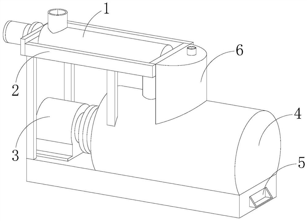
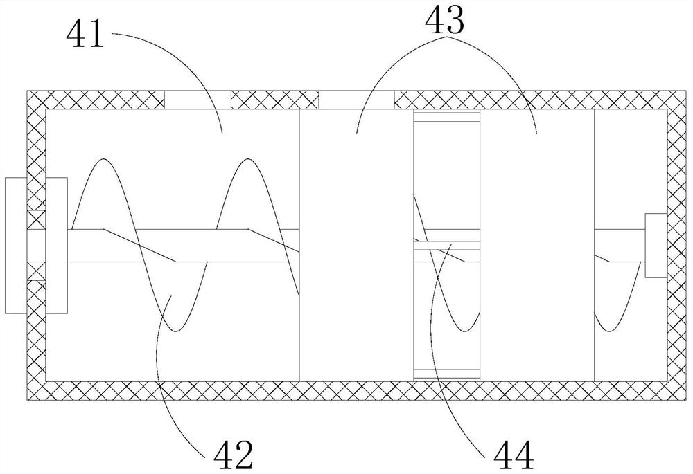
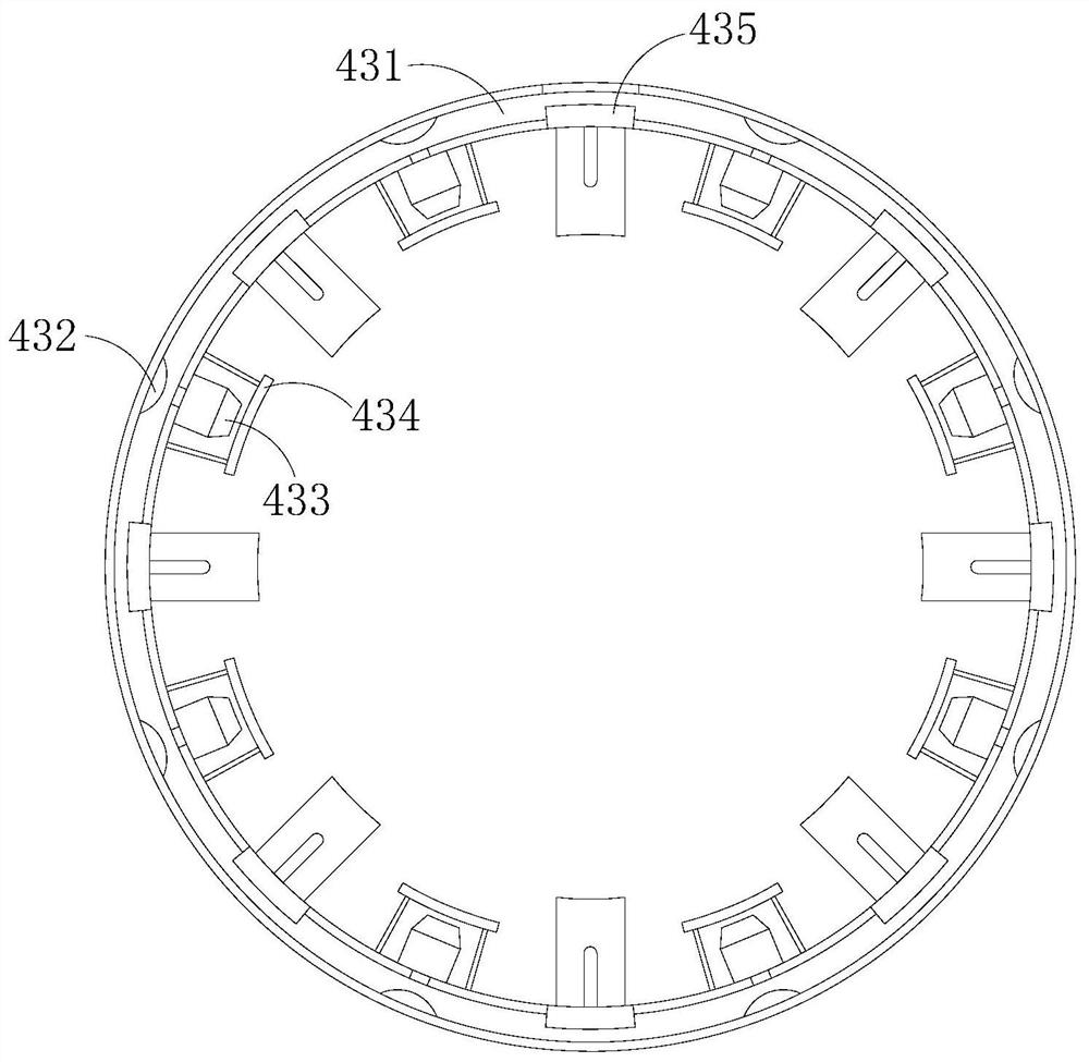
[0023] The present invention is a microbial fermentation equipment for sludge treatment. Its structure includes a feed pipe 1, a support frame 2, a motor 3, a fermentation device 4, a discharge port 5 and a ventilation chamber 6. 2 top, and the lower end of the support frame 2 is welded with the top of the fermentation device 4, the output end of the motor 3 rotates synchronously with the inside of the fermentation device 4, the lower right end of the fermentation device 4 is embedded with a discharge port 5, and the ventilation chamber 6 is on the upper left The end is welded with the right end of the support frame 2, and the lower end of the ventilation chamber 6 is installed on the middle end of the top of the fermentation device 4 and communicates with each other. Through the pipe 44, a screw agitator 42 is installed at the inner middle end of the fermentation tank 41, and the screw agitator 42 rotates synchr...

Embodiment 2

[0030] as attached Image 6 to the attached Figure 7 shown:

[0031] The swing mechanism 435 includes a rotating shaft 35a, a guide rod 35b, and a baffle plate 35c. The rotating shaft 35a is provided inside the ventilation plate 431, and the rotating shaft 35a is installed on the upper end of the baffle plate 35c. The guide rod 35b The upper end is fixed to the inner side wall of the ventilation plate 431, and the lower end of the guide rod 35b passes through the inner middle end of the baffle plate 35c by clearance fit. 35c has the effect of blocking the flow of the sludge during the stirring process, thereby improving the fermentation time of the sludge.

[0032] The baffle plate 35c includes a plate body c1 and a partition plate c2. The upper end of the plate body c1 is provided with a rotating shaft 35a, and the plate body c1 is located on the inner side wall of the ventilation plate 431. The partition c2, the partition c2 is installed inside the plate body c1 at an in...


PUM


Abstract

The invention discloses microbial fermentation equipment for sludge treatment. The structure of the microbial fermentation equipment comprises a feed pipe, a support frame, a motor, a fermentation device, a discharge port and a ventilation chamber, wherein the feed pipe is mounted at the top of the support frame, and the lower end of the support frame is welded with the top of the fermentation device; when gas flows in a conduction pipe, the gas can quickly enter a nozzle throughextrusion of a convex block, so that the air is uniformly discharged into the fermentation tank; an opening and closing plate is closed through torsion reset of a torsion shaft, so that external sludge is prevented from entering the nozzle to cause blockage, and the comprehensiveness of aerobic thermophilic bacteria in contact with oxygen is improved; and through rotation of the rotation shaft, a spoiler is elastically extruded on the guide rod, and the angle of the spoiler is changed, so that the effect of the spoiler for blocking the sludge in the stirring process is improved, and the contact time of the sludge and aerobic thermophilic bacteria is prolonged.

Description

technical field [0001] The invention relates to the technical field of microbial fermentation, more particularly, to a microbial fermentation device for sludge treatment. Background technique [0002] Sludge aerobic fermentation is a harmless, volume-reducing and stabilizing sludge comprehensive treatment technology, also known as aerobic composting technology. The organic matter in the sludge is decomposed to form a substance similar to humus soil, but since the sludge is in the process of stirring and fermenting, by adding aerobic thermophilic bacteria, and aerobic thermophilic bacteria need to consume oxygen, through aeration Oxygen is introduced into the fermentation equipment, and the oxygen introduced by aeration circulates unevenly in the fermentation equipment. At the same time, stirring easily causes the flow of sludge and aerobic thermophilic bacteria in the fermentation equipment to be too fast, resulting in oxygen and good quality. The effect of full contact wit...

Claims


Application Information

Patent Timeline
IPC IPC(8): C02F11/02B01F7/08
CPCC02F11/02
Inventor 许晓宇
Owner 青岛瀚丰生物科技有限公司
Learn More