Supercharge Your Innovation With Domain-Expert AI Agents!

Easily-installed single-base self-standing regulating valve

A control valve, self-supporting technology, applied in the field of control valves, can solve the problems of increasing the installation difficulty of the control valve, low installation efficiency, and high maintenance and installation costs of the control valve, and achieve the effects of simple installation, improved installation efficiency, and reduced maintenance and installation costs.

Inactive Publication Date: 2021-09-17
杭州普昌科技有限公司
View PDF1 Cites 0 Cited by
  • Summary
  • Abstract
  • Description
  • Claims
  • Application Information

AI Technical Summary

Problems solved by technology

[0006] Aiming at the deficiencies of the prior art, the present invention provides an easy-to-install single-seat self-supporting regulating valve, which solves the low installation efficiency between the water guide hole and the pipeline of the regulating valve, and the installation method of connecting flanges still needs to use The use of special tools increases the difficulty of installation of the control valve and the high cost of maintenance and installation of the control valve

Method used


Image

  • Easily-installed single-base self-standing regulating valve
  • Easily-installed single-base self-standing regulating valve
  • Easily-installed single-base self-standing regulating valve

Examples


Embodiment 1

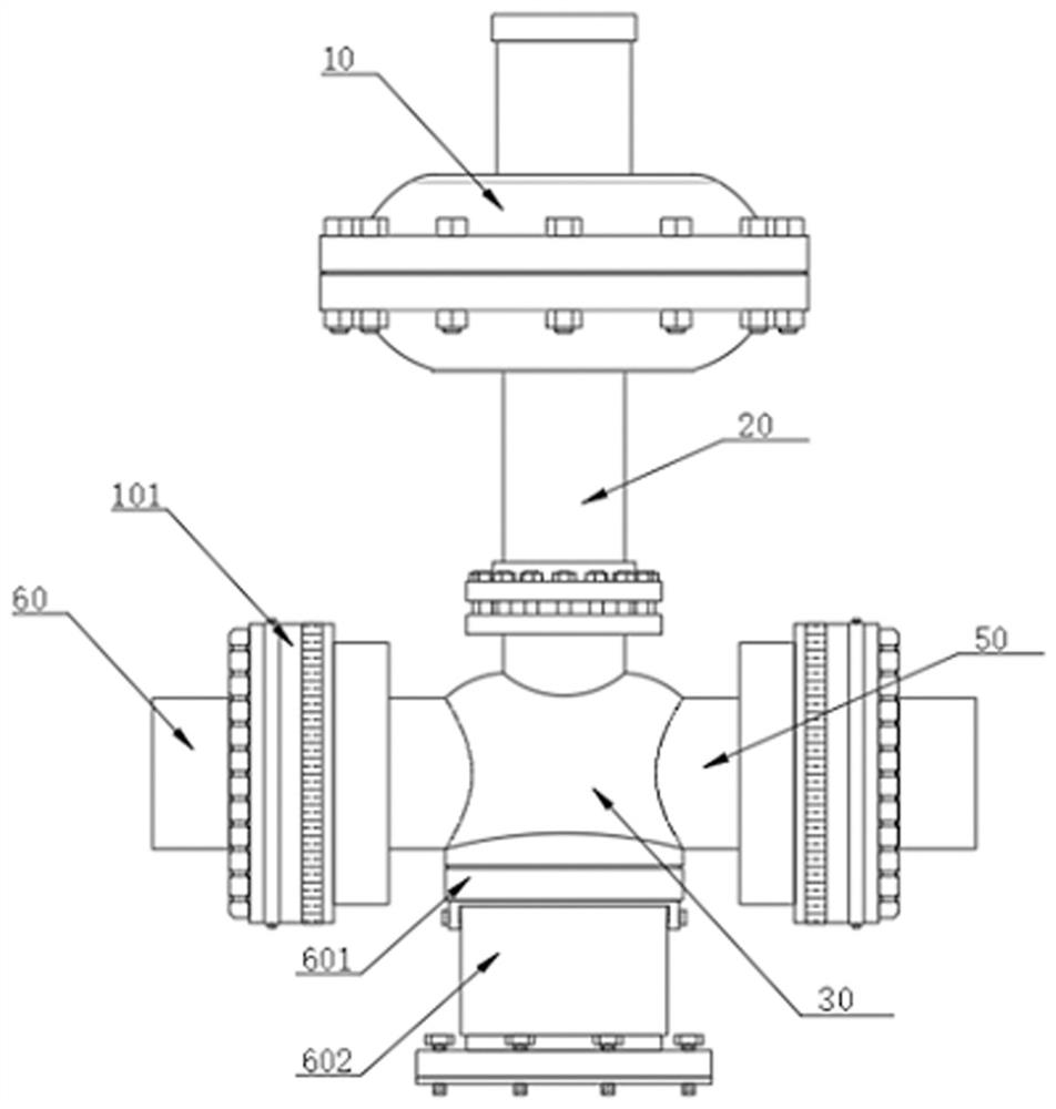
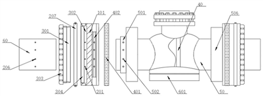
[0041] see Figure 1-3 As shown, an easy-to-install single-seat self-supporting regulating valve includes a valve cover 10, a sleeve 20 and a valve body 30. The bottom of the valve cover 10 is welded to the top end of the sleeve 20, and the bottom end of the sleeve 20 is connected by The flange is connected to the top of the valve body 30, the inside of the valve body 30 is provided with a valve core 40, and both ends of the valve body 30 are connected with a water conduit 50, and one end of the two water conduits 50 is connected with a water delivery pipeline 60, and The water pipe 50 and the water delivery pipe 60 are coaxially arranged, the pipe diameters of the water guide pipe 50 and the water delivery pipe 60 are the same, and a connection mechanism is arranged between the water guide pipe 50 and the water delivery pipe 60;

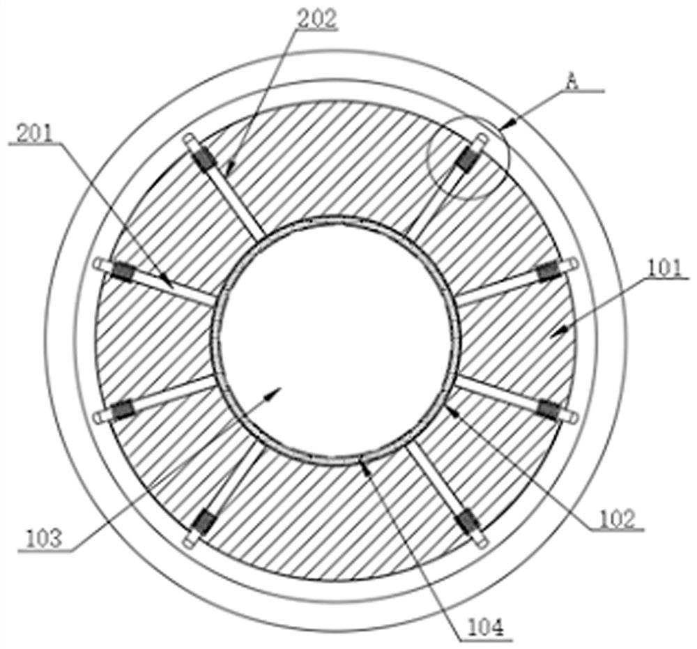
[0042] The connection mechanism includes a connecting sleeve 101, both sides of the connecting sleeve 101 are provided with installation grooves 10...

Embodiment 2

[0044] see Figure 2-4 As shown, both sides of the connection sleeve 101 in the present invention are provided with push rod assemblies, wherein the push rod assembly includes movable rods 201, and the movable rods 201 are arranged in several groups inside the connection sleeve 101, and several groups of movable rods 201 are about The central axis of the connecting sleeve 101 is arranged in an equiangular distribution, and the inside of the connecting sleeve 101 is provided with a plurality of movable grooves 202 matched with the movable rods 201, and several movable rods 201 are respectively located in several movable grooves 202. The inside of the movable groove 202 is provided with a connecting groove 203, and the surface of the movable rod 201 located at the inside of the connecting groove 203 is provided with a connecting ring 204. One 205, and the spring one 205 is sleeved on the surface of the movable rod 201, and the spring one 205 is used to realize the automatic rese...

Embodiment 3

[0046] see figure 2 As shown, in the present invention, a limit assembly is provided on the left side of the peripheral surface of the connecting sleeve 101, wherein the limit assembly includes a limit ring 301, and a chute is opened inside the limit ring 301, and the inner diameter of the left side of the limit ring 301 is less than The inner diameter of the right side, the inside of the connecting sleeve 101 is provided with a limiting groove 302, and the limiting ring 301 is rotated inside the limiting groove 302, and one end of the left movable rod 201 located inside the connecting sleeve 101 extends to the inside of the limiting groove 302 , the left side of the connection sleeve 101 is threadedly connected to the limit sleeve 303, and the limit sleeve 303 is used to enter the length inside the connection sleeve 101 to adjust the position where the limit ring 301 enters the limit groove 302. The inner wall of the limit ring 301 and the movable rod 201 is in contact with ...


PUM


Abstract

The invention discloses an easy-to-install single-base self-standing regulating valve, and relates to the technical field of regulating valves. The easy-to-install single-base self-standing regulating valve comprises a valve cover, a sleeve and a valve body, wherein the bottom of the valve cover is connected to the top end of the sleeve. According to the easy-to-install single-base self-standing regulating valve, one end of a water guide pipe is inserted into a connecting sleeve, a connecting column is inserted into a movable groove, and the water guide pipe makes contact with a sealing gasket, so that installing and connecting of the water guide pipe inside the connecting sleeve are completed, a positioning ring is rotationally arranged inside a positioning groove, the top end of a movable rod makes contact with the interior of an arc-shaped groove, then the installation between the water guide pipe and the connecting sleeve can be conveniently completed, compared with traditional flange type installation, installation between the connecting sleeve and the water guide pipe does not need to use any tool, the stability of installation between the water guide pipe and the connecting sleeve can be doubly guaranteed through the connecting column and a fixing ring, the installing efficiency between the water guide pipe and the connecting sleeve is effectively improved, and then the maintenance and installing cost of the regulating valve is reduced.

Description

technical field [0001] The invention relates to the technical field of regulating valves, in particular to an easy-to-install single-seat self-supporting regulating valve. Background technique [0002] Regulating valve, also known as control valve, accepts the control signal output by the regulating control unit and uses power operation to change the final control element of process parameters such as medium flow, pressure, temperature and liquid level. In order to make the regulating valve more stable, it is more convenient to use. Convenience, a single-seat vacuum self-supporting regulating valve came out of the trend; [0003] In the existing Chinese patent CN108869871A, a single-seat vacuum self-supporting regulating valve is proposed. In this scheme, the setting of the fixed column and the rotating groove is adopted to realize the installation and connection between the main body of the regulating valve and the regulating block, but in general Under normal circumstance...

Claims


Application Information

Patent Timeline
Patent Type & Authority Applications(China)
IPC IPC(8): F16K27/00F16K51/00F16L23/036F16L23/18
CPCF16K27/00F16K51/00F16L23/036F16L23/18
Inventor 赵亚南朱加宝
Owner 杭州普昌科技有限公司
Features
  • R&D
  • Intellectual Property
  • Life Sciences
  • Materials
  • Tech Scout
  • Unparalleled Data Quality
  • Higher Quality Content
  • 60% Fewer Hallucinations
Learn More