
Bending type protection pipe for smart home

A smart home, bending technology, applied in the direction of elbows, siphons, pipe components, etc., can solve problems such as damage, unstable water purifiers, etc., and achieve the effect of convenient use

Inactive Publication Date: 2021-09-17
胡序程
View PDF0 Cites 0 Cited by
  • Summary
  • Abstract
  • Description
  • Claims
  • Application Information

AI Technical Summary

Problems solved by technology

[0005] The purpose of the present invention is to solve the problem that most traditional water purifiers are easily damaged due to unstable water pressure, and to provide a smart household bending protection tube that can protect the water purifier

Method used


Image

  • Bending type protection pipe for smart home
  • Bending type protection pipe for smart home
  • Bending type protection pipe for smart home

Examples


Embodiment 1

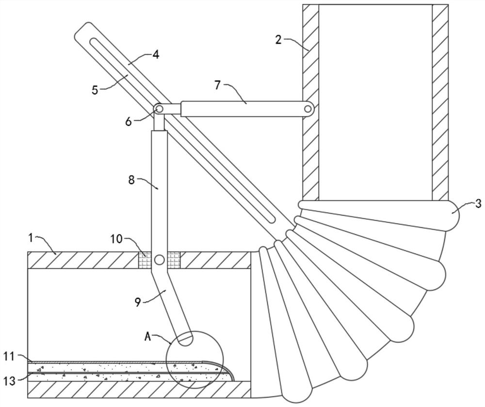
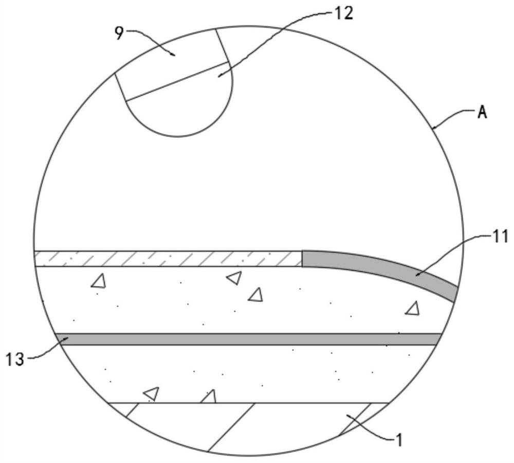
[0026] like Figure 1-2 As shown, a bending protection tube for smart home, including a fixed tube 1, one end of the fixed tube 1 is provided with a rotating tube 2, the fixed tube 1 and the rotating tube 2 are fixedly connected with a coaxial corrugated tube 3, It is worth mentioning that the diameter of the rotating tube 2 is larger than that of the fixed tube 1, which can rapidly reduce the flow rate of the water flowing from the fixed tube 1 to the rotating tube 2. 2 coaxial fixed connections.

[0027] The side wall of the corrugated pipe 3 is fixedly connected with a fixed bar 4, and the fixed bar 4 is provided with a slide rail 5, and the slide rail 5 is slidably connected with a slide button 6, and the side wall of the rotating tube 2 is rotatably connected with a rotating rod 7, and the other part of the rotating rod 7 One end is rotatably connected with the slide button 6 .

[0028] The side wall of the fixed pipe 1 is rotatably connected with a rotating connecting ...

Embodiment 2

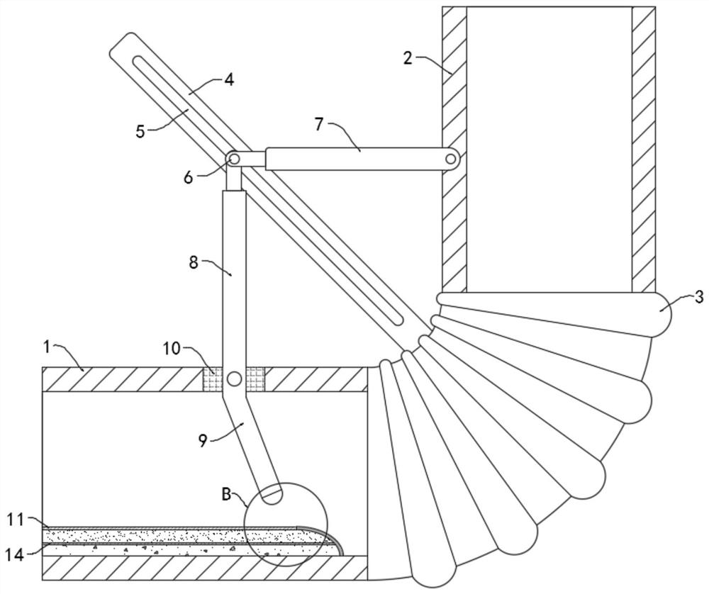
[0037] like Figure 3-4 As shown, the difference between this embodiment and Embodiment 1 is that a horizontally arranged elastic plate 14 is fixedly connected to the strip-shaped elastic bag 11, and the elastic plate 14 divides the strip-shaped elastic bag 11 into an upper chamber 15 and a lower chamber 16. , the upper cavity 15 is filled with the magnetic powder which is mixed with the permanent magnet block 12 different poles, and the lower cavity 16 is filled with silver bromide powder.

[0038] In this embodiment, the elastic plate 14 is transparent. Under normal circumstances, the magnetic powder in the upper cavity 15 is evenly spread on the elastic plate 14 with a larger area, and the light can shine into the lower cavity 16 through the gap between the magnetic powder, so that The silver bromide powder in lower chamber 16 meets light and takes place following reaction: AgBr=Ag+Br 2 , the bromine gas generated by the reaction will expand the elastic plate 14 , so that ...


PUM


Abstract

The invention belongs to the field of smart home, and particularly relates to a bending type protection pipe for smart home. The bending type protection pipe comprises a fixed pipe, a rotating pipe is arranged at one end of the fixed pipe, a coaxially-arranged corrugated pipe is fixedly arranged between the fixed pipe and the rotating pipe in a communicating manner, a fixed strip is fixedly connected to the side wall of the corrugated pipe, a sliding rail is arranged on the fixed strip, and a sliding knob is slidably connected in the sliding rail. By arranging an adjusting mechanism, the larger the water flow in the fixed pipe is, the larger the impact rotation angle of a deflection rod is, the smaller the included angle between a rotating connecting rod and the fixed strip is, that is, the sliding knob can be driven to slide towards the upper end of the fixed strip, and therefore one end of a rotating rod is driven to slide towards the upper end of the fixed strip, the included angle between the fixed pipe and the rotating pipe is gradually reduced from a flat angle under driving of the rotating rod and the rotating connecting rod, the larger the water flow speed is, the larger the rotating angle is, automatic adjustment can be conducted according to the water flow pressure, use is convenient, and effective protection can be provided for a water purifier.

Description

technical field [0001] The invention belongs to the field of smart home, and in particular relates to a bent protection tube for smart home. Background technique [0002] With the continuous improvement of living standards, water purifiers have gradually spread to thousands of households. Household water purifiers generally refer to small filters, which filter impurities in water through filter elements to achieve the purpose of purification, and filter elements need to be replaced regularly. [0003] Most traditional water purifiers are directly connected to faucets or water supply pipes during use. Since the upper floors of the community often need to be pressurized for water supply, but the lower floors do not, this also leads to water in the household water supply pipes. The water pressure is often in a state of constant change, and the water purifier is generally equipped with low-pressure switches and other components. Unstable water pressure, especially high water pre...

Claims


Application Information

Patent Timeline
Patent Type & Authority Applications(China)
IPC IPC(8): F16L27/11F16L43/00F16L55/02F16L55/045
CPCF16L27/11F16L43/00F16L55/02F16L55/045
Inventor 胡序程
Owner 胡序程
Learn More