
An intelligent DC power distribution switch and its working method

A technology of DC power distribution and switching, which is applied in substation/switch layout details, panel/switching station circuit devices, measuring electricity, etc. It can solve the high stability and safety requirements of DC power distribution switches and the intelligentization of DC power distribution network The level is not high, failure or accident prevention and other problems can be realized, and the effect of realizing the reasonable distribution of electricity, improving the degree of intelligence, and protecting safety

Active Publication Date: 2021-10-29
NINGBO TIAN AN SMART GRID TECH CO LTD
View PDF0 Cites 0 Cited by
  • Summary
  • Abstract
  • Description
  • Claims
  • Application Information

AI Technical Summary

Problems solved by technology

[0003] However, at present, photovoltaic power generation is related to weather conditions such as four seasons, day and night, and cloudy weather due to solar radiation, resulting in unstable power generation. The following problems are prone to occur in the process of photovoltaic DC power distribution:
[0004] (1) Since the rated current of a single power storage device or other load is a fixed value, when the power generation is too large, a single power storage device or other load may be overloaded
[0005] (2) Due to the instability of power generation, its output current is also unstable, which requires higher stability and safety of DC power distribution switches
[0006] (3) Due to the low level of intelligence of the existing DC distribution network, failures or accidents cannot be prevented in time

Method used


Image

  • An intelligent DC power distribution switch and its working method
  • An intelligent DC power distribution switch and its working method
  • An intelligent DC power distribution switch and its working method

Examples


Embodiment Construction

[0062] Hereinafter, the present application will be further described in conjunction with specific implementation methods. It should be noted that, on the premise of not conflicting, the various embodiments or technical features described below can be combined arbitrarily to form new embodiments.

[0063] In the description of this application, it should be noted that for orientation words, such as the terms "center", "horizontal", "longitudinal", "length", "width", "thickness", "upper", "lower" , "Front", "Back", "Left", "Right", "Vertical", "Horizontal", "Top", "Bottom", "Inner", "Outer", "Clockwise", "Counterclockwise ” and other indication orientations and positional relationships are based on the orientations or positional relationships shown in the drawings, which are only for the convenience of describing the application and simplifying the description, rather than indicating or implying that the device or element referred to must have a specific orientation, use a speci...


PUM


Abstract

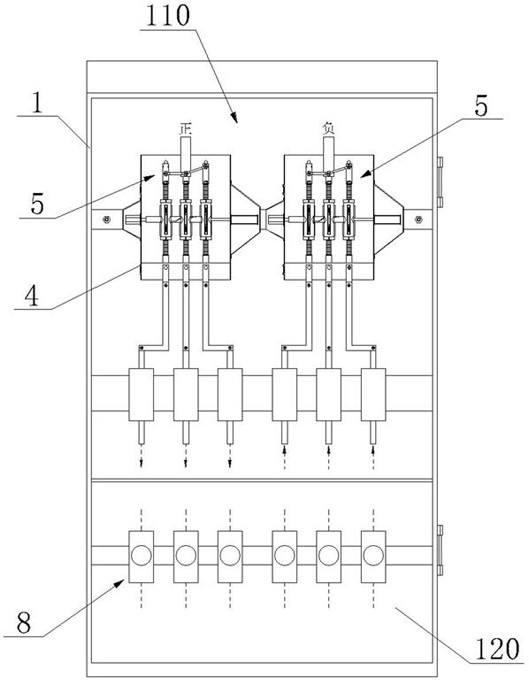
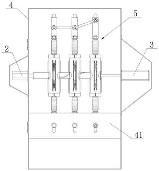
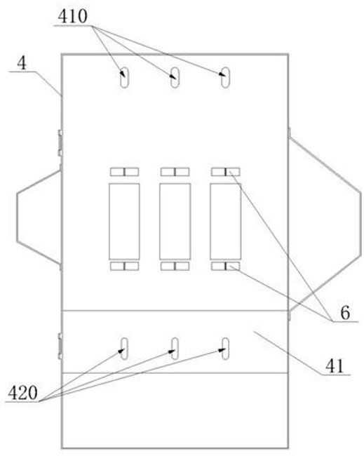
The application discloses an intelligent DC power distribution switch, which includes a cabinet, a switch device, a drive device and a monitoring system. The switch device is installed in the cabinet. The switch device includes a drive shaft and a plurality of switch assemblies, and the plurality of switch assemblies are connected in parallel to the circuit. Among them, the drive shaft cooperates with multiple switch components; the monitoring system is suitable for detecting the electrical signals of the two connecting plate components, and controls the start of the drive device according to the detected electrical signal changes, and then drives the drive shaft to control the switching of multiple switch components. Open or close. Beneficial effects of the application: the number of switch components connected to the circuit can be controlled according to the change of electrical signals in the circuit, so as to protect the safety of the entire circuit, and at the same time, it is also possible to judge whether the load is faulty or not according to the abnormal electrical signals at both ends of the switch components , and disconnect the switching components connected to the faulty load, further improving the safety of the entire circuit.

Description

technical field [0001] The application relates to the field of electric equipment, in particular to a DC power distribution switch. Background technique [0002] With the rapid development of distributed photovoltaics, more distributed photovoltaics will be connected to the urban power grid in the future. Under the conditions of the existing AC distribution network, the photovoltaics generated by DC power generation need to undergo DC / DC and DC / AC two-stage conversion. It is inevitable to introduce a large number of converters to the AC distribution network, which causes waste and reduces efficiency, and its random fluctuations also have a direct impact on the power grid. Therefore, how to connect distributed photovoltaics to the grid more effectively, conveniently and reliably has become an urgent problem to be solved. The DC distribution network can realize the flexible access of distributed photovoltaics, omit the DC / AC inversion process, and reduce the power conversion ...

Claims


Application Information

Patent Timeline
Patent Type & Authority Patents(China)
IPC IPC(8): H02B1/32H02B1/24H02H7/22G01R31/327H01H21/54H01H21/36H02J13/00
CPCH02B1/32H02B1/24H02H7/222G01R31/3275H01H21/54H01H21/36H02J13/00036Y04S10/20Y02E60/00
Inventor 欧阳道生胡昀实徐鹏赟
Owner NINGBO TIAN AN SMART GRID TECH CO LTD
Learn More