
LED silicon controlled rectifier dimming quick response circuit and LED lighting device

A fast-response, silicon dimming technology, applied to electrical components, etc., can solve problems such as the inability to achieve fast dimming, and achieve the effects of fast startup, fast response, and fast dimming

Pending Publication Date: 2021-09-17
上海奥简微电子科技有限公司
View PDF1 Cites 0 Cited by
  • Summary
  • Abstract
  • Description
  • Claims
  • Application Information

AI Technical Summary

Problems solved by technology

However, the above scheme cannot achieve fast dimming

Method used


Image

  • LED silicon controlled rectifier dimming quick response circuit and LED lighting device
  • LED silicon controlled rectifier dimming quick response circuit and LED lighting device
  • LED silicon controlled rectifier dimming quick response circuit and LED lighting device

Examples


Embodiment Construction

[0033] The present invention will be described in detail below in conjunction with specific embodiments. The following examples will help those skilled in the art to further understand the present invention, but do not limit the present invention in any form. It should be noted that those skilled in the art can make several changes and improvements without departing from the concept of the present invention. These all belong to the protection scope of the present invention.

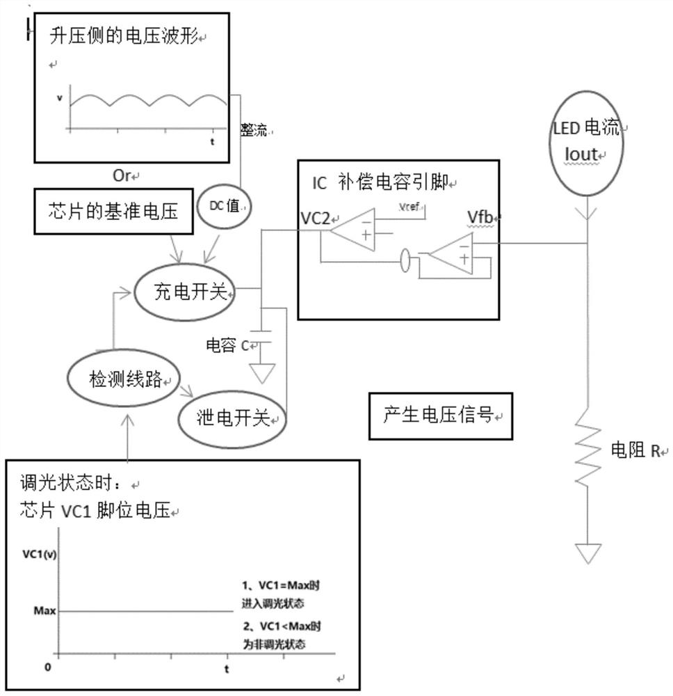
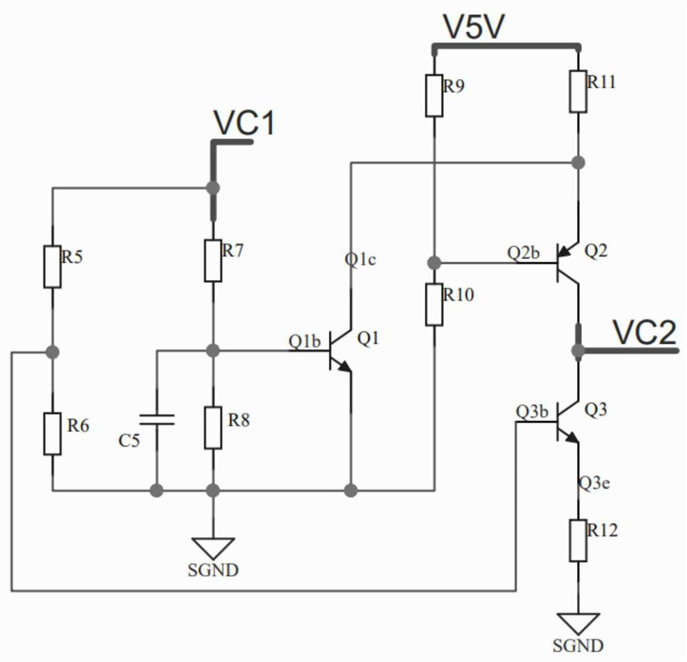
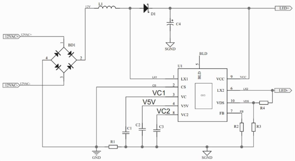
[0034] Such as Figure 1 to Figure 3 As shown, according to the LED thyristor dimming fast response circuit and LED lighting device provided by the present invention, there is a function on the dimming circuit: the potential of the VC pin of the chip will be at 0-4V during operation, and when it can be When the silicon controlled dimming, when the voltage of VC reaches the maximum 4V, it will start dimming, specifically:

[0035] 1. The present invention charges the compensation capacitor VC2 through a...


PUM


Abstract

The invention provides an LED silicon controlled rectifier dimming quick response circuit and an LED lighting device. The circuit comprises an input voltage, a charging circuit, a reference voltage, a detection circuit, an on-off circuit, a leakage circuit and an output voltage, wherein the input voltage is connected with the input end of the detection circuit, one output end of the detection circuit is connected with the charging circuit through the on-off circuit, and the other output end of the detection circuit is connected with the leakage circuit; the output voltage is arranged between the charging circuit and the leakage circuit; the reference voltage supplies power to the charging circuit; when the on-off circuit is disconnected, the charging circuit charges the output voltage; when the on-off circuit is connected, the discharge circuit discharges the output voltage. According to the invention, the problem of quick response of the output current during dimming of the LED silicon controlled rectifier, namely the technical problem of how to quickly charge and discharge the compensation voltage, is solved, and the LED current can be quickly responded and changed during dimming of the silicon controlled rectifier.

Description

technical field [0001] The invention relates to a dimming circuit, in particular to an LED thyristor dimming fast response circuit and an LED lighting device. Background technique [0002] In the existing MR16 dimming application boost+linear topology circuit, the potential change of the LED current is set by the potential of the compensation capacitor. Through the voltage waveform of LED-, detect the Sine voltage waveform potential to charge and discharge the compensation capacitor, and realize the adjustment of LED current. In the MR16 thyristor dimming application, the LED current response is slow when the thyristor is fast dimming, and cannot keep up with the speed of the angle change of the thyristor. [0003] Since the value of the compensation capacitor needs to be 4.7uf-22uF, a relatively stable voltage can be obtained, and the corresponding output current value will be stable; but because the charging current / discharging current inside the compensation capacitor is...

Claims


Application Information

Patent Timeline
Patent Type & Authority Applications(China)
IPC IPC(8): H05B45/10
CPCH05B45/10
Inventor 叶桐林
Owner 上海奥简微电子科技有限公司
Learn More