Water pipe fixing mechanism
A technology for fixing mechanisms and water pipes, applied in workpiece clamping devices, manufacturing tools, etc., can solve problems such as water pipe deformation, achieve the effects of avoiding impact force, reducing deformation, and ensuring accuracy
- Summary
- Abstract
- Description
- Claims
- Application Information
AI Technical Summary
Problems solved by technology
Method used
Image
Examples
Embodiment approach
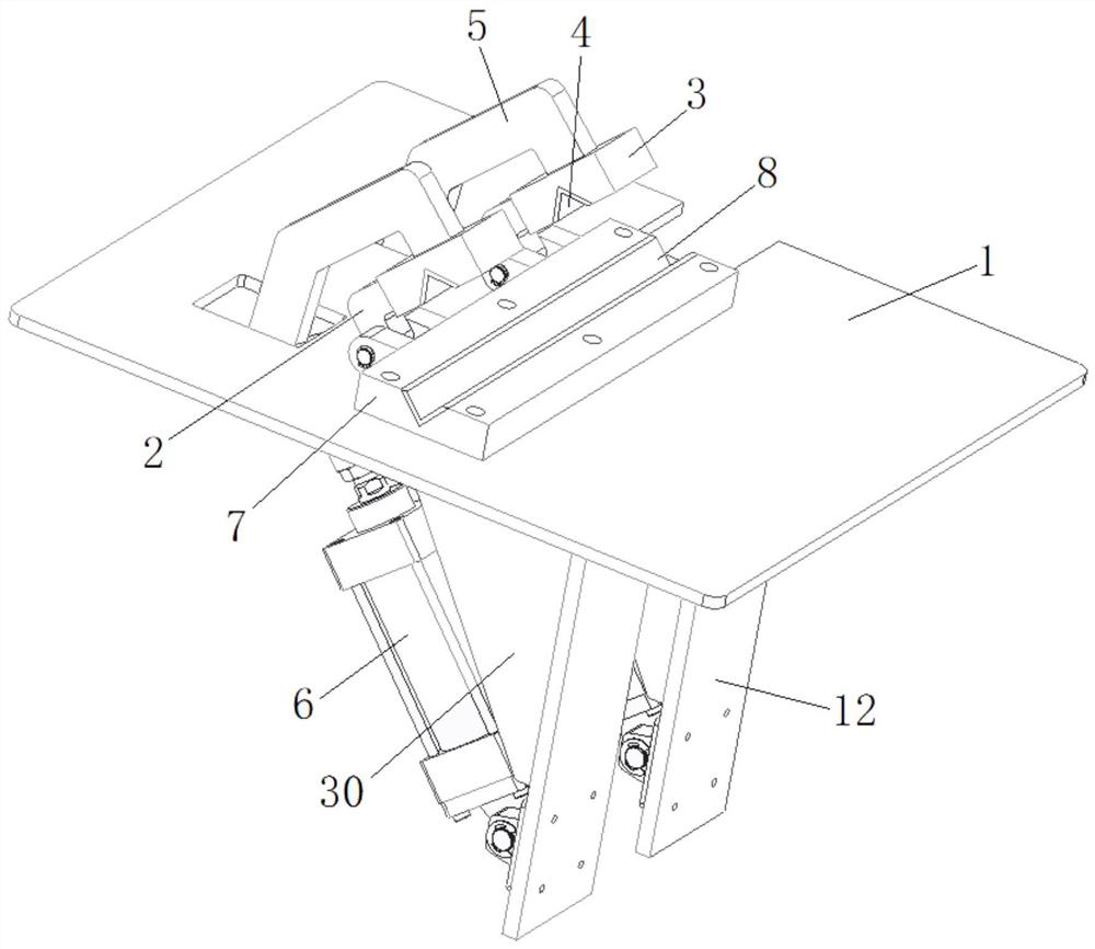
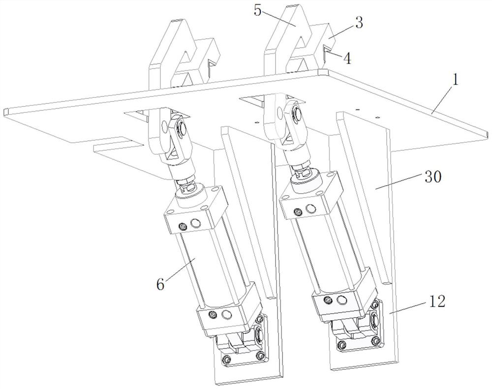
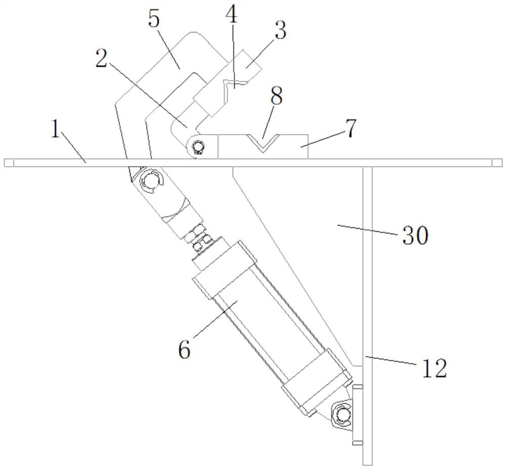
[0043] Such as Figures 1 to 4A specific implementation of the shown water pipe fixing mechanism includes: a placement board 1 , a support board 12 vertically connected to the bottom surface of the placement board 1 , and a placement block 7 arranged on the top of the placement board 1 . One side of the placement block 7 is connected with a bump, and the bottom of the bump is arranged on the placement board 1 . One end of the connecting rod 2 is rotatably connected with the projection through a rotating shaft, and the other end of the connecting rod 2 is connected with a pressing block 3 . A groove 4 is provided on the side of the pressing block 3 close to the placement plate 1, and a placement groove 8 is provided on the placement block 7, and both the groove 4 and the placement groove 8 are V-shaped grooves. The side of the pressing block 3 far away from the placement board 1 is connected with a pressing rod 5, and the other end of the pressing rod 5 penetrates through the ...
Embodiment 2
[0050] Such as Figures 5 to 7 A specific implementation of the nozzle flaring structure shown includes: the above-mentioned water pipe fixing mechanism, and the flaring head 11, the slider 10 and the driver 9 connected in sequence, and the flaring head 11 is arranged facing the water pipe fixing mechanism.
[0051] Such as Figure 5 As shown, the driving end of the driver 9 is fixedly connected to the rear end of the slider 10 , and the flared head 11 is fixedly connected to the front end of the slider 10 . Driven by the driver 9, the slide block 10 drives the flaring head 11 to enter the end of the nozzle to be flared, and at this moment the flaring head 11 is in a positioning state; the driving end of the driver 9 remains motionless, after a certain period of time, the driver 9 Drive the slide block 10 again, and the slide block 10 drives the flaring head 11 to enter the inside of the pipe opening to be flared, so that the pipe mouth to be flared is flared; Oral 11 back i...
Embodiment 3
[0057] Such as Figure 8 A specific implementation of the shown pipe joint installation device includes the above-mentioned pipe mouth flaring structure and pipe joint installation structure. The flaring head 11 of the pipe mouth flaring structure and the installation head 18 of the pipe joint installation structure are all set towards the water pipe fixing mechanism, and the pipe mouth to be flared is flared by using the pipe mouth flaring structure, and the pipe joint is fixed by using the pipe joint installation structure. Installed on the nozzle after flaring.
[0058] As an alternative embodiment, the lower end of the pressing rod 5 is connected with a push plate, the driving end of the first driving part 6 is movably connected to the lower surface of the pushing plate, and the side of the first driving part 6 away from the driving end is fixed to the support plate 12 Connect, the rotating shaft that connecting rod 2 is rotatably connected with projection is provided wit...
PUM
 Abstract
Description
Claims
Application Information
 - R&D
- Intellectual Property
- Life Sciences
- Materials
- Tech Scout
- Unparalleled Data Quality
- Higher Quality Content
- 60% Fewer Hallucinations
Browse by: Latest US Patents, China's latest patents, Technical Efficacy Thesaurus, Application Domain, Technology Topic, Popular Technical Reports.
© 2025 PatSnap. All rights reserved.Legal|Privacy policy|Modern Slavery Act Transparency Statement|Sitemap|About US| Contact US: help@patsnap.com


