
Laser cutting machine for top cover of transformer box

A laser cutting machine, transformer box technology, applied in laser welding equipment, metal processing equipment, welding equipment and other directions, can solve the problems of cumbersome tightening of the top cover of the transformer box, reducing factory production efficiency, and danger of fatigue work. Avoid flying debris, fast positioning, and improve work efficiency

Inactive Publication Date: 2021-09-21
衡阳市广源线路器材有限公司
View PDF6 Cites 0 Cited by
  • Summary
  • Abstract
  • Description
  • Claims
  • Application Information

AI Technical Summary

Problems solved by technology

[0002] The top cover of the transformer box usually needs to be cut during the processing process. The unstable position of the top cover during cutting may affect its cutting quality. The top cover of the transformer box has different shapes and sizes, so the fastening of its position is very difficult. It is cumbersome, and manual operation is generally used in the processing and cutting process. Workers who work for a long time may cause physical fatigue, which will not only reduce the production efficiency of the factory, but also fatigue work is very dangerous. Although the cutting methods of existing cutting equipment are becoming more and more There are many, but the positioning structure still cannot meet the needs of various functions, so now a new solution is needed to solve these problems, such as: the process of installing and fixing the top cover of the transformer box is troublesome and time-consuming, which affects the processing efficiency

Method used


Image

  • Laser cutting machine for top cover of transformer box

Examples


Embodiment Construction

[0018] The following will clearly and completely describe the technical solutions in the embodiments of the present invention with reference to the accompanying drawings in the embodiments of the present invention. Obviously, the described embodiments are only some, not all, embodiments of the present invention. Based on the embodiments of the present invention, all other embodiments obtained by persons of ordinary skill in the art without making creative efforts belong to the protection scope of the present invention.

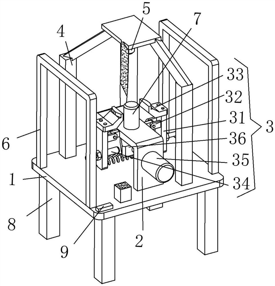
[0019] see figure 1 , the present invention provides a technical solution: a transformer box roof laser cutting machine, including a mounting plate 1, a connecting seat 2 and a fixing mechanism 3;

[0020] Mounting plate 1: The connecting seat 2 is fixedly connected to the surface of the middle position, the appearance of the connecting seat 2 is an inverted U shape, the upper surface of the middle position of the mounting plate 1 is fixedly connected to the s...


PUM


Abstract

The invention discloses a laser cutting machine for a top cover of a transformer box. The laser cutting machine comprises a mounting plate, a connecting seat and a fixing mechanism. The connecting seat is fixedly connected to the surface of the middle position of the mounting plate, the appearance of the connecting seat is in an inverted U shape, a supporting frame is fixedly connected to the upper surface of the middle position of the mounting plate, protruding blocks are fixedly connected to the middle positions of the two sides of the supporting frame, and a laser cutter is connected to the supporting frame. The fixing mechanism comprises movable rods, connecting blocks, clamped connection heads, transmission rods, an electric telescopic rod and a transmission block, the two movable rods are arranged, the connecting blocks are fixedly connected to the surfaces of the middle positions of the movable rods, the connecting blocks are movably connected with the protruding blocks on the two sides of the supporting frame correspondingly, and the upper ends of the movable rods are fixedly connected. The process of fixing is quite simple and convenient, consumed time is short, and the machining efficiency is improved.

Description

technical field [0001] The invention relates to the technical field of laser processing equipment, in particular to a laser cutting machine for the top cover of a transformer box. Background technique [0002] The top cover of the transformer box usually needs to be cut during the processing process. The unstable position of the top cover during cutting may affect its cutting quality. The top cover of the transformer box has different shapes and sizes, so the fastening of its position is very difficult. It is cumbersome. Manual operation is generally used in the processing and cutting process. Workers who work for a long time may cause physical fatigue, which will not only reduce the production efficiency of the factory, but also cause fatigue work. Although the existing cutting equipment cutting methods are becoming more and more There are many, but the positioning structure still cannot meet the needs of various functions, so a new solution is needed to solve these problem...

Claims


Application Information

Patent Timeline
Patent Type & Authority Applications(China)
IPC IPC(8): B23K26/38B23K26/70
CPCB23K26/38B23K26/702
Inventor 杨晓文刘艳
Owner 衡阳市广源线路器材有限公司
Learn More