Small pile foundation vibration resistance reduction type efficient pile pulling device for hydraulic engineering construction

A technology for water conservancy projects and small piles, which is applied in infrastructure engineering, sheet pile walls, buildings, etc. It can solve the problems of reducing pile pulling efficiency, easily damaged equipment, and large frictional resistance, so as to improve pile pulling efficiency and reduce usage scenarios , the effect of friction reduction

Inactive Publication Date: 2021-09-21
JIAXING JINXILAI TECH CO LTD
View PDF0 Cites 0 Cited by
  • Summary
  • Abstract
  • Description
  • Claims
  • Application Information

AI Technical Summary

Problems solved by technology

The hydraulic pile puller uses its pile clamp to clamp the pile head, and the hydraulic cylinder forces the pile clamp to lift it up for a certain distance, and the pile is pulled out section by section. It is suitable for clay, sandy soil or soil containing a small amount of gravel. Pulling I-beam or section steel piles in the layer also uses mechanical methods to pull out piles, that is, the hoist is driven by a motor, and the piles are forced out of the ground by the pulling force of the wire rope pulley block. It is bulky and has low pile extraction efficiency, and is only suitable for construction in soft ground. The double-action air hammer is used to extract piles. The hammer body is inverted, fixed on the pile head, and hung under the rigging. First, the pile head in the soil is shaken to reduce the Check the tightness between the pile and the soil, then start the air hammer, hammer and vibrate upwards, tighten the rigging, and gradually pull out the pile, and can pull out concrete piles and other piles in various soil layers
The existing pile extractor equipment mainly clamps the pile head through the clamping mechanism when the pile head is fixed, and lifts and pulls out the pile through hydraulic drive or large-scale engineering equipment such as a crane. The equipment occupies a large area, which is not conducive to The construction of water conservancy projects cannot be carried out in a narrow space, and some small piles can only be pulled out manually, which is time-consuming and laborious
[0004] In addition, in the pile pulling operation, the traditional chuck structure can only carry out pressure clamping on both sides of the pile head, the clamping strength is low, and it is easy to slip and fall off, and the size of the chuck structure is difficult to adjust, and it cannot be adapted to different piles. Large and small pile head structures have low adaptability. During the pile pulling operation, the dynamic chuck drives the pile to break away from the soil layer, but the pile itself does not move, but the surface friction of the pile and the soil layer cause friction The resistance is relatively large, and it is difficult to effectively apply the pile pulling effect by only relying on the pull-out traction of the chuck, which reduces the pile-pull efficiency and affects the mechanical pull-out speed. Large friction is easy to damage the equipment, and there are certain defects.

Method used


Image

  • Small pile foundation vibration resistance reduction type efficient pile pulling device for hydraulic engineering construction
  • Small pile foundation vibration resistance reduction type efficient pile pulling device for hydraulic engineering construction
  • Small pile foundation vibration resistance reduction type efficient pile pulling device for hydraulic engineering construction

Examples


Embodiment Construction

[0031] Next, the technical solutions in the embodiments of the present invention will be apparent from the embodiment of the present invention, and it is clearly described, and it is understood that the described embodiments are merely embodiments of the present invention, not all of the embodiments. Based on the embodiments of the present invention, there are all other embodiments obtained without making creative labor without making creative labor premises.

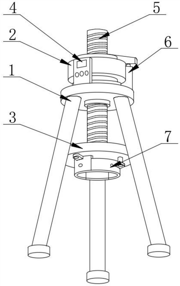
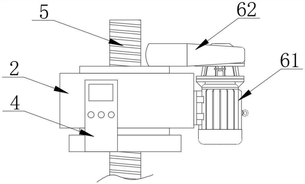
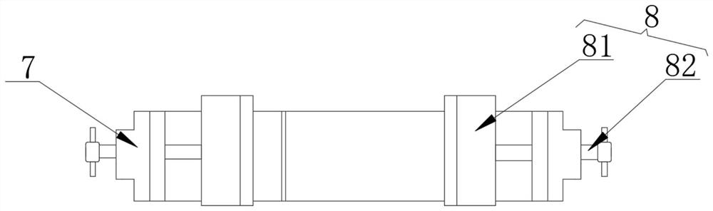
[0032] Append figure 1 Adherent Figure 8Embodiments of the present invention provides a highly efficient hydraulic engineering construction equipment small pile pulling pile vibration drag type, comprising a support stand 1, pulling the pile driving mechanism 2 and a drive mechanism 6, pulling the pile driving mechanism 2 is fixed by a screw attached to the stand supporting a top surface, a driving mechanism 6 is fixedly mounted to the side of the support stand 1, the surface of the pulling pile driving mechanism 2 is fixed...


PUM


Abstract

The invention discloses a small pile foundation vibration resistance reduction type efficient pile pulling device for hydraulic engineering construction, and particularly relates to the field of hydraulic engineering. The small pile foundation vibration resistance reduction type efficient pile pulling device comprises a supporting vertical frame, a pile pulling driving mechanism and a driving mechanism, wherein the pile pulling driving mechanism is fixedly arranged on the top surface of the supporting vertical frame through a screw rod, the driving mechanism is fixedly arranged on one side of the supporting vertical frame, a control panel is fixedly arranged on the surface of the pile pulling driving mechanism, a driving screw rod is movably arranged on the surfaces of the pile pulling driving mechanism and the supporting vertical frame, and the bottom of the driving screw rod is rotationally connected with a movable pile pulling foundation table in a sleeved mode. According to the scheme, the pile pulling device adopts a pile head keeping mechanism and a vibration clamping plate structure, the pile head keeping mechanism and the vibration clamping plate are used for carrying out surrounding type clamping structure on a pile sinking pile head, an annular structure is formed on the periphery of the pile head by utilizing the pile head keeping mechanism, the distance between the vibration clamping plates is adjusted through thread engagement with a clamping screw rod so as to clamp the pile head, the pile head keeping mechanism and the vibration clamping plate structure can be matched with pile heads with different shapes and sizes, and the practicability of the pile pulling device is improved.

Description

Technical field [0001] The present invention relates to the field of water conservancy engineering, and more particularly, the present invention specifically a small pile-based vibration-resistant drainage type high-efficiency pile-based vibration damping type. Background technique [0002] In order to prevent the foundation of the foundation, in the excavation operation in the water conservancy project, a large number of column piles are usually entered around the construction site, and in the process of building water conservancy projects, in order to ensure the smooth implementation of new project projects, it is necessary to affect the project. The old pile of the project is removed, thereby avoiding potential safety hazards to the rear construction, and usually use the pile driver in the process of removal of the old pile to remove the piles, the traditional pile is the pile The surrounding filler digs part of the excavator and then uses the lifting equipment to remove the c...

Claims


Application Information

Patent Timeline
Patent Type & Authority Applications(China)
IPC IPC(8): E02D9/02E02D9/00
CPCE02D9/02E02D9/00
Inventor 蒋晓伟
Owner JIAXING JINXILAI TECH CO LTD
Why Eureka
Try Eureka