
Oil filtering and cooling device for hydraulic oil cylinder

A technology of a cooling device and a hydraulic cylinder, which is applied in the field of hydraulic cylinders, can solve the problems of reduced service life of hydraulic cylinders, reduced service life of hydraulic cylinders, reduced cleanliness of hydraulic oil, etc., and achieves the effect of increasing service life and realizing cooling effect

Inactive Publication Date: 2021-09-21
何德业
View PDF0 Cites 1 Cited by
  • Summary
  • Abstract
  • Description
  • Claims
  • Application Information

AI Technical Summary

Problems solved by technology

[0003] During the use of the hydraulic cylinder, due to the impurities contained in the hydraulic oil itself and the impurities contaminated by the piston rod during the telescopic movement, the cleanliness of the hydraulic oil will gradually decrease. During the telescopic process of the piston rod, impurities will easily enter the piston rod and the cylinder. Between the inner walls, the wear is caused to the two, resulting in a reduction in the life of the hydraulic cylinder, and the continuous increase in the temperature of the hydraulic oil will also affect the physical properties of the hydraulic cylinder such as precision and strength, reducing the service life of the hydraulic cylinder

Method used


Image

  • Oil filtering and cooling device for hydraulic oil cylinder
  • Oil filtering and cooling device for hydraulic oil cylinder
  • Oil filtering and cooling device for hydraulic oil cylinder

Examples


Embodiment

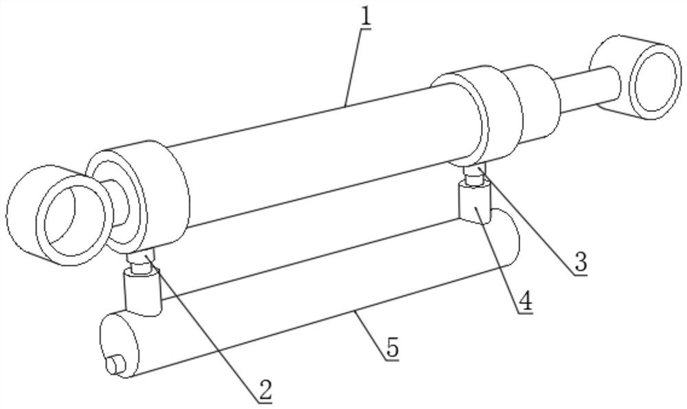
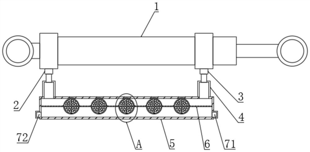
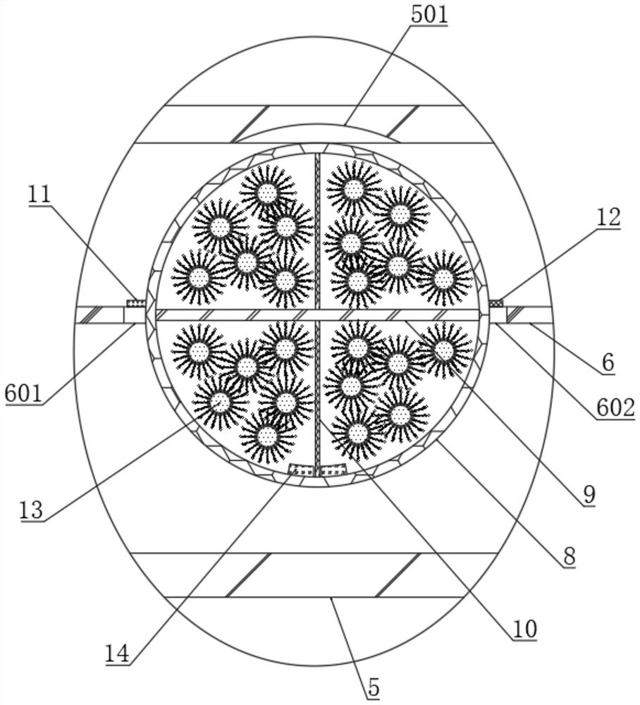
[0043] see figure 1 and figure 2 , an oil filtering and cooling device for a hydraulic cylinder, comprising a cylinder body 1 and a double-chamber pipe 5 connected to the cylinder body 1, the cylinder body 1 is fixedly connected with an oil injection pipe 2 and an oil outlet pipe 3, and the oil injection pipe 2 and the outlet pipe Both the oil pipe 3 and the double-lumen tube 5 are fixedly connected with a connecting pipe 4, and the connecting pipe 4 communicates with the inside of the double-lumen pipe 5, and the inside of the double-lumen pipe 5 is fixedly connected with a partition 6, and the partition 6 divides the inner portion of the double-lumen pipe 5. The upper part is for the flow of hydraulic oil, and the lower part holds the cooling and cleaning oil, and the cooling and cleaning oil is the same type of oil as the hydraulic oil, so that even if part of the cooling and cleaning oil is mixed into the hydraulic oil, it is not easy The use of the cylinder 1 is affecte...


PUM


Abstract

The invention discloses an oil filtering and cooling device for a hydraulic oil cylinder, and belongs to the field of hydraulic oil cylinders. The oil filtering and cooling device comprises a cylinder body and a double-cavity pipe connected to the cylinder body, an oil injection pipe and an oil outlet pipe are fixedly connected to the cylinder body, connecting pipes are fixedly connected between the oil injection pipe and the double-cavity pipe and between the oil outlet pipe and the double-cavity pipe, and the connecting pipes are communicated with the interior of the double-cavity pipe. Filter balls capable of rotating reversely are arranged in the double-cavity pipe, half of the filter balls is located in hydraulic oil, and the other half of the filter balls is located in cooling clean oil, so that on one hand, the hydraulic oil in the flowing process is continuously filtered, and on the other hand, the filtered filter balls automatically rotate reversely by 180 degrees, and the filtered parts are transferred into the cooling clean oil for cooling and self-cleaning, and therefore, the continuous and effective filtering process of the hydraulic oil is realized through the filter balls, and meanwhile, the cooling effect on the hydraulic oil is also realized, and the service life of the cylinder body is greatly prolonged.

Description

technical field [0001] The invention relates to the field of hydraulic cylinders, more specifically, to an oil filtering and cooling device for hydraulic cylinders. Background technique [0002] A hydraulic cylinder is a hydraulic actuator that converts hydraulic energy into mechanical energy and performs linear reciprocating motion (or swing motion). It has simple structure and reliable operation. When it is used to realize reciprocating motion, the deceleration device can be eliminated, and there is no transmission gap, and the motion is stable, so it is widely used in various mechanical hydraulic systems. The output force of the hydraulic cylinder is proportional to the effective area of ​​the piston and the pressure difference on both sides; the hydraulic cylinder is basically composed of a cylinder barrel and a cylinder head, a piston and a piston rod, a sealing device, a buffer device and an exhaust device. Buffers and exhausts are application specific and others are...

Claims


Application Information

Patent Timeline
Patent Type & Authority Applications(China)
IPC IPC(8): F15B21/0423F15B21/041
CPCF15B21/0423F15B21/041
Inventor 何德业
Owner 何德业
Learn More