
Gate flow cross section flow measuring method

A water-passing section and gate technology, which is applied in the measurement of flow/mass flow, measuring device, fluid velocity measurement, etc., can solve the problem of lack of specific methods for flow velocity measurement, limit the application of gate water measurement, and cannot cover flow velocity, etc. Continuous online measurement, automatic measurement, high-precision calculated effect

Inactive Publication Date: 2021-09-21
唐山现代工控技术有限公司
View PDF7 Cites 4 Cited by
  • Summary
  • Abstract
  • Description
  • Claims
  • Application Information

AI Technical Summary

Problems solved by technology

The above-mentioned defects have plagued industry personnel for a long time, but there has been no better solution for many years, which limits the application of gate water measurement to a certain extent
The applicant previously applied for 202022291714.6 "A Doppler Water Conservancy Gate Flow Measuring Device", which has the following problems: 1. The Doppler flow velocity sensor uses a single measuring point to measure the flow velocity, which cannot cover the flow velocity at each point of the entire vertical line, and the error 2. The lack of a specific method for flow velocity measurement limits the application of this technology to a certain extent

Method used


Image

  • Gate flow cross section flow measuring method
  • Gate flow cross section flow measuring method
  • Gate flow cross section flow measuring method

Examples


Embodiment Construction

[0027] The present invention will be further described through the embodiments below in conjunction with the accompanying drawings.

[0028] A method for measuring flow at a cross-section of a gate, comprising the following steps:

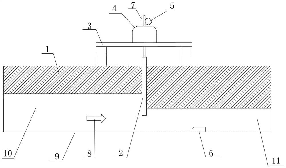
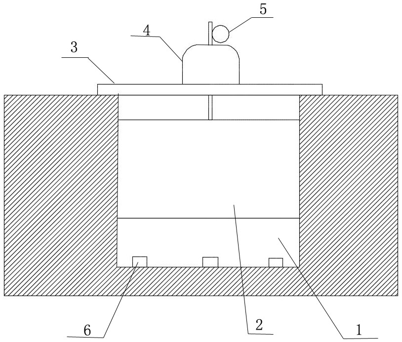
[0029] ① Doppler vertical profile flow velocity sensors are installed on the bottom surface behind the gate, and are arranged in multiple vertical lines, with at least one quantity;

[0030] ②The Doppler vertical profile flow velocity sensor faces the ram and emits an ultrasonic Doppler multi-point flow velocity detection beam obliquely upward. The number and spacing of the flow velocity detection points on the beam can be set, due to the beam angle during manufacture It has been determined that the actual velocity value of each point on the sag line of the ram is the cosine value of the beam angle 12;

[0031] ③ Within the coverage of the detection beam of the Doppler vertical profile flow velocity sensor, the flow velocity detection point includ...


PUM


Abstract

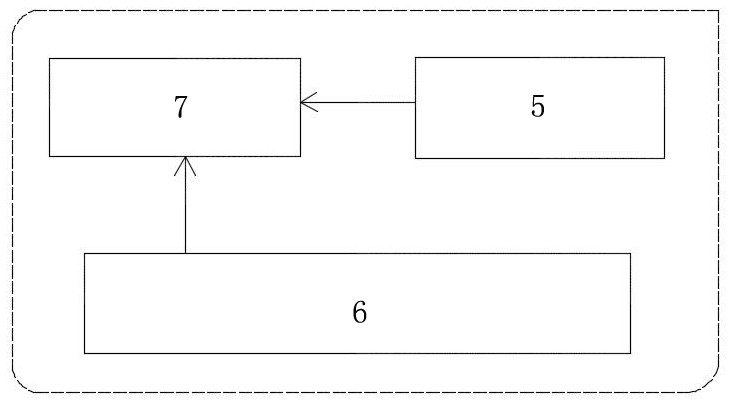
The invention relates to a gate flow cross section flow measurement method, and belongs to the technical field of water conservancy gate flow measurement. According to the technical scheme, within the coverage range of detection beams of a Doppler vertical profile flow velocity sensor, a flow velocity detection point comprises vertical flow velocity below the lower edge of a flashboard, namely within the opening range of the flashboard, and also comprises vertical flow velocity above the lower edge of the flashboard, namely beyond the opening range of the flashboard; a gate measurement and control instrument (7) determines the opening degree of the gate, namely the position of the lower edge of the flashboard through the gate level sensor (5) so as to determine that the lower edge and below of the flashboard are effective flow velocity measurement points to participate in flow velocity calculation, the upper edge of the flashboard is invalid flow velocity measurement points, and the measured flow velocity value is thrown away; and stratified flow measurement is carried out in an effective flow measurement range. The method has the beneficial effects that layered flow measurement is carried out in an effective flow measurement range, the influence of turbulent flow above the lower edge of the flashboard on the lockage flow velocity is avoided, continuous online measurement of the lockage flow can be realized, the lockage flow can be calculated with high precision, and management of a management department is facilitated.

Description

technical field [0001] The invention relates to a method for measuring flow at a water cross section of a gate, which belongs to the technical field of flow measurement of water conservancy gates. Background technique [0002] At present, the calculation formulas used in the existing flow measurement methods of water conservancy gates generally have relatively large errors. The above-mentioned defects have plagued industry personnel for a long time, but there has been no better solution for many years, which limits the application of gate water measurement to a certain extent. The applicant previously applied for 202022291714.6 "A Doppler Water Conservancy Gate Flow Measuring Device", which has the following problems: 1. The Doppler flow velocity sensor uses a single measuring point to measure the flow velocity, which cannot cover the flow velocity at each point of the entire vertical line, and the error 2. The lack of a specific method for flow velocity measurement limits ...

Claims


Application Information

Patent Timeline
Patent Type & Authority Applications(China)
IPC IPC(8): G01P5/24G01F1/66
CPCG01P5/241G01F1/66
Inventor 张喜于子朔于树利张家铭
Owner 唐山现代工控技术有限公司
Learn More