Frequency converter with simplified pre-charging circuit
A frequency converter and circuit technology, applied in the field of frequency converters, can solve the problems of high cost and large total volume.
- Summary
- Abstract
- Description
- Claims
- Application Information
AI Technical Summary
Problems solved by technology
Method used
Image
Examples
Embodiment Construction
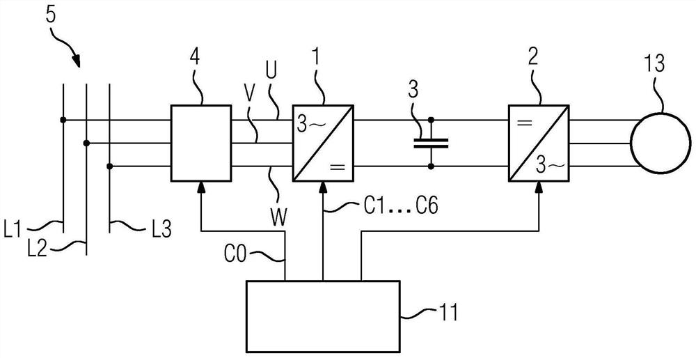
[0034] according to figure 1 , the frequency converter has a rectifier 1 on the input side. A further device 2 is arranged downstream of the rectifier 1 on the output side. The frequency converter also has at least one backup capacitor 3 which is arranged between the rectifier 1 and the further device 2 . Another device is usually designed as an inverter. In this case we speak of an intermediate circuit converter. However, this further device can also be designed differently, for example as a direct voltage consumer, a direct voltage network, a photovoltaic system or an energy store.
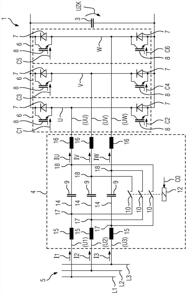
[0035] The rectifier 1 has U, V, W phases on the input side, which are connected to L1 , L2 , L3 of a supply network 5 via a front circuit 4 . Both the rectifier 1 and the supply network 5 are thus polyphase, ie each have a plurality of phases U, V, W or L1 , L2 , L3 . The phases U, V, W of the rectifier 1 are referred to below as input-side phases U, V, W to distinguish them from the phase...
PUM
 Abstract
Description
Claims
Application Information
 - R&D
- Intellectual Property
- Life Sciences
- Materials
- Tech Scout
- Unparalleled Data Quality
- Higher Quality Content
- 60% Fewer Hallucinations
Browse by: Latest US Patents, China's latest patents, Technical Efficacy Thesaurus, Application Domain, Technology Topic, Popular Technical Reports.
© 2025 PatSnap. All rights reserved.Legal|Privacy policy|Modern Slavery Act Transparency Statement|Sitemap|About US| Contact US: help@patsnap.com


